 English
Introduction
In our digital lives, network cables serve as the invisible bridge that connects us to the world of information. Though simple in appearance, their internal structure embodies sophisticated electromagnetic principles. This article takes you inside the physical medium known as "twisted pair cable"—from its unique twisted structure to standardized wiring rules, as well as its evolution from early telephone lines to modern network cabling.
Understanding Network Cables
The conductors within a network cable are twisted in pairs at a specific density. When transmitting electrical signals, the electromagnetic waves radiated by each pair cancel each other out, effectively eliminating interference—hence the name "twisted pair." This design ensures that each pair has distinct twist pitches, winding directions, and winding counts to minimize crosstalk.
Origin of Twisted Pair Cables
Early internet access relied on telephone lines for dial-up connections, with bandwidth below 56 Kbps. Users connected the RJ11 plug of a telephone line to the Line port of a modem, which then linked to the computer.
Telephone lines today come in 2-core, 4-core, 6-core, and even 8-core versions. A typical household only needs a 2-core cable for voice calls. Corporate or multi-line systems often use 4-core telephone lines to support both telephony and broadband services, while digital phone systems may require 6 cores. These early telephone lines used the RJ11 connector. To maintain expandability, RJ11 was designed with 4 or 6 pins, although only two pins were commonly active.
Later, ADSL and DSL technologies emerged. They kept the same physical telephone-line medium but adopted different signaling methods, leading to faster speeds and ushering in the "broadband" era. Eventually, local service providers and users began adopting fiber-based access systems—partially or fully—further boosting transmission speeds.
To achieve even better performance, the industry introduced twisted-pair cabling and the RJ45 standard. When drafting the RJ45 specification, designers considered backward compatibility with the existing RJ11 interface.
They created an 8-pin RJ45 connector: the original concept allocated the central two pins for telephone lines, four pins for data lines, and reserved the remaining two pins for future performance upgrades.
Standard Wiring Sequence
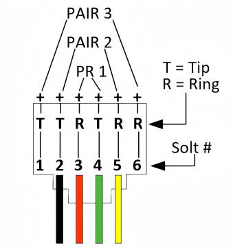
Among the 8 cores in the cable, telephone lines must use the two center-most cores—specifically, the 4th and 5th cores. Data transmission primarily relies on cores 1st, 2nd, 3rd, and 6th. To prevent network connectivity issues caused by arbitrary wiring, two unified international wiring standards were established: TIA/EIA 568A and TIA/EIA 568B. Both standards firmly establish the core role of pins 4 and 5.
According to the 568A and 568B standards, the functions of each pin in an RJ45 connector are as follows:
- Pins 1 & 2: Transmit signals (Tx+ / Tx−)
- Pins 3 & 6: Receive signals (Rx+ / Rx−)
- Pins 4, 5, 7, & 8: Bidirectional lines, reserved and unused in 100 Mbps networks.
To minimize interference, the standards mandate that:
- Pins 1 and 2 must form a twisted pair.
- Pins 3 and 6 must form another twisted pair.
- Pins 4 and 5 must be twisted together.
- Pins 7 and 8 must also be twisted together.
In essence, the 568A and 568B standards are functionally identical—the only difference lies in the color sequence of the 8 cores when terminating the RJ45 connector.
| Pin # | 1 | 2 | 3 | 4 | 5 | 6 | 7 | 8 |
|---|---|---|---|---|---|---|---|---|
| T568A | Green/White | Green | Orange/White | Blue | Blue/White | Orange | Brown/White | Brown |
| T568B | Orange/White | Orange | Green/White | Blue | Blue/White | Green | Brown/White | Brown |
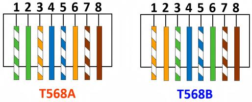
When network cables are connected following the standard wiring sequence, they exhibit minimal interference and optimal transmission stability, with particularly noticeable benefits over longer cable runs. In practical network engineering implementations, the 568B standard is more commonly adopted.
Although twisted pair cables contain eight conductors, current widely-used Fast Ethernet (100BASE-TX) networks only utilize four of them - specifically wires 1, 2, 3, and 6 (orange-white, orange, green-white, green) - which handle signal transmission and reception. Wires 4,5 and 7,8 remain reserved. It's only in Gigabit Ethernet (1000BASE-T) or higher-speed networks that all eight wires, including 4,5 and 7,8, are employed for data transmission.
Why Two Wiring Standards Exist?
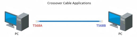
The emergence of both T568A and T568B standards originated from the fact that early network cards and switches didn't support Auto MDI/MDI-X. When connecting identical network devices, a crossover cable was required—with one end terminated as T568A and the other as T568B—to ensure proper signal transmission.
Modern switches and networking equipment now universally support automatic crossover detection, making manual crossover cables obsolete. Consequently, the industry has gradually standardized on T568B straight-through wiring.
RJ45 Connector Termination Methods
1. Crossover Wiring
Crossover wiring uses T568A on one end and T568B on the other. This method was traditionally employed for interconnecting devices of the same type, such as:
- PC network card to PC network card
- Hub regular port to hub regular port
- Switch to switch
2. Straight-through Wiring
Straight-through wiring uses either T568A or T568B on both ends. This is primarily used for connecting dissimilar devices:
- PC network card to hub regular port
- Hub regular port to hub uplink port
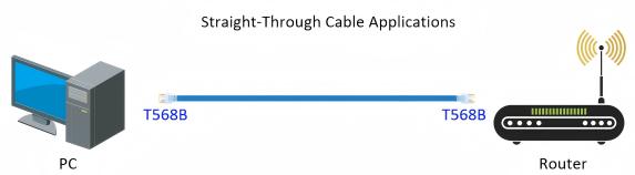
In contemporary practice, T568B straight-through wiring dominates most scenarios. For short-distance use, it is sufficient for both ends to have the same wiring sequence. However, for long-distance transmission, it is recommended to strictly adhere to the standard wiring sequence to ensure signal quality and transmission stability.
