 English
In intelligent computing centers built around large-scale GPU clusters, network bandwidth, latency, and reliability directly determine the efficiency of AI training, big data processing, and other tasks. As a core component connecting servers, switches, and storage systems, optical modules play a pivotal role in unlocking the performance of intelligent computing centers. This article systematically explains how optical modules build an efficient and stable interconnection system for intelligent computing centers, covering core application scenarios, deployment key points, network adaptation strategies, and implementation processes.
1.Application Scenarios and Technological Evolution of Optical Modules
The high interconnection demands of intelligent computing centers drive continuous advancement in optical module scenario adaptation and technology—shifting from "functional" to "high-performance and efficient."
1.1 Three Core Application Scenarios
- Server - Switch Interconnection: Enabling High-Speed GPU Cluster Communication
GPU clusters (e.g., NVIDIA DGX H100) in intelligent computing centers rely on optical modules for seamless switch connectivity, ensuring bottleneck-free data transmission. For instance, DGX H100 clusters use 400G OSFP DR4/VR4 modules to connect to the 800G OSFP 2DR4/2VR4 ports of Quantum-2 switches, supporting real-time multi-GPU data interaction within nodes.
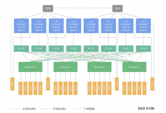
Figure 1: NVIDIA DGX H100 Server Interconnect Architecture Diagram
- Long-Distance Switch Interconnection: Facilitating Distributed Training
For cross-data center tasks (e.g., multi-site large model joint training), single-mode optical modules are critical. Modules with transmission distances of 100m, 500m, 2km, or 10km enable long-distance switch interconnection, breaking physical barriers and ensuring distributed training synchronization.
- Storage - Computing Interconnection: Enabling Lossless, Low-Latency Transmission
Connections between storage networks and computing nodes require protocols like RoCE (RDMA over Converged Ethernet) or InfiniBand (IB), with optical modules as the core carrier for these protocols. For example, InfiniBand networks achieve 200Gbps transmission via QSFP56 HDR modules, meeting the demand for high-speed storage data delivery to computing nodes and avoiding I/O bottlenecks.
1.2 Evolution of Speed, Form Factor, and Technical Routes
Speed Upgrade: 800G as MainstreamCurrently, 800G optical modules (in QSFP-DD/OSFP form factors) have become the "standard" in intelligent computing centers. With the deployment of high-performance servers like NVIDIA GB200/GB300, demand for 1.6T transceiver modules is emerging. In the future, 3.2T modules will adopt CPO (Co-Packaged Optics) to enhance bandwidth density.
Form Factor: QSFP-DD vs OSFP
QSFP-DD: Supports 8 channels × 100Gbps, backward compatible with QSFP28/QSFP56, suitable for high-density and low-power scenarios.
OSFP: Larger size, supports higher power consumption, ideal for high-bandwidth devices. For example, NVIDIA Quantum-2 switches are paired with dual-port OSFP modules.
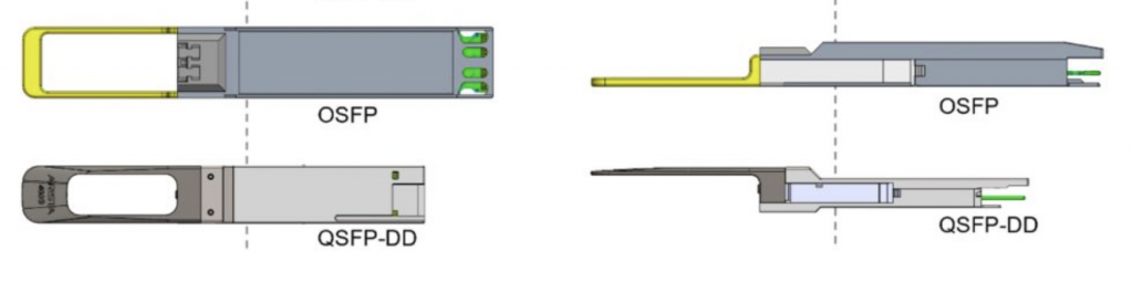
Figure 2: OSFP and QSFP-DD Comparison
Technical Route: LPO as Preferred Choice
LPO (Linear Pluggable Optics) reduces the power consumption of optical modules by 27% and latency by 17% by removing traditional DSP chips. It meets the low-power, low-latency needs of intelligent computing centers and has become a mainstream technical route.
1.3 Three Key Performance Indicators
- Bandwidth and Speed: The single-channel speed of optical transceivers has upgraded from 25G (NRZ encoding) to 100G/200G (PAM4 encoding), supporting both multimode fiber (MMF, short-distance) and single-mode fiber (SMF, long-distance).
- Latency and Reliability: The bit error rate (BER) must be <1E-12 (meeting RoCEv2 protocol requirements) and comply with telecom-grade standards (e.g., IPEC), ensuring >99.999% availability.
- Power Consumption and Heat Dissipation: 800G OSFP modules consume ~16-20W. Liquid cooling (reducing temperature by 15°C) or optimized rack heat dissipation is required to avoid overheating-related performance issues.
2.Key Points for Optical Module Deployment
Optical transceiver deployment requires strict control over four aspects to ensure coordination with intelligent computing center equipment:
2.1 Selection and Compatibility: Accurate Matching as Premise
Speed Matching: Optical module speed must match device ports (e.g., 800G switch ports need 800G modules) to avoid speed reduction or alarms.
Form Factor Compatibility: Different architectures have distinct needs (e.g., InfiniBand networks use dual-port OSFP 800G modules for Quantum-2 switches and OSFP400G or QSFP112 modules for ConnectX-7 network adapters; RoCE networks require pre-verified transcever interoperability between switches and network adapters).
Protocol Compliance: InfiniBand modules must follow IBTA standards and pass interoperability tests (e.g., AICPLIGHT 400G modules for NVIDIA devices); RoCE modules need IEEE 802.3ck support.
2.2 Signal Integrity: Optimizing Links to Reduce Loss
Optical Power and Fiber Selection: MMF (850nm) for <100m (e.g., 800G OSFP SR8); SMF (1310/1550nm) for 500m-2km (e.g., 800G DR8). Ensure optical power is within the module receiving sensitivity range (-9 to -3dBm).
Signal Compensation: LPO modules rely on switch ASIC dynamic compensation; verify automatic tuning capabilities of optical modules from different manufacturers pre-deployment.
2.3 Reliability and Operation: Full-Cycle Assurance
Testing and Certification: Optical modules must pass BER, extinction ratio, eye diagram, and aging tests (e.g., telecom-grade certification) and provide CNAS/CMA reports.
Monitoring and Early Warning: Use DDM (Digital Diagnostic Monitoring) to track temperature, power consumption, and optical power; set alarms (e.g., >85°C) and deploy intelligent systems for minute-level fault location.
2.4 Power Consumption and Heat Dissipation: Green Operation
Power Optimization: Prioritize LPO modules (50% lower power than traditional DSP modules), reducing overall machine power by 25%-40%.
Liquid Cooling: Immerse modules (e.g., MPO interface) in coolant; verify sealing and compatibility.
Heat Dissipation Design: Increase fan speed or use liquid-cooled backplanes for high-density racks (e.g., fully configured 800G modules) to avoid elevated BER.
3.Optical Module Matching for InfiniBand and RoCE Architectures
The two mainstream network architectures in intelligent computing centers—InfiniBand and RoCE—have significantly different requirements for optical modules, networking equipment, and configuration. Targeted matching schemes must be designed.
3.1 InfiniBand Network: High Bandwidth, Low Latency Solution
Widely used in high-end GPU clusters, with matching strategies as follows:
Core Equipment Selection
InfiniBand Switches: NVIDIA Quantum-2 (supporting NDR 400G/800G) must be paired with dual-port OSFP optical modules (e.g., MMS4X00-NM, 1310nm, 500m).
Network Adapters: ConnectX-7 supports OSFP or QSFP112 modules (e.g., flat-top 400G single-port OSFP), while BlueField-3 DPU only supports QSFP112 modules.
Fiber and Connectors: MMF + MPO-12/APC for 3-50m; SMF + MPO-16/APC for 500m-2km (e.g., NVIDIA DGX H100 clusters).
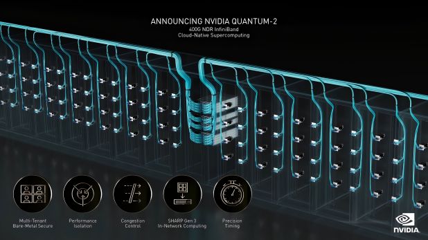
Figure 3: NVIDIA QUANTUM-2 400G NDR InfiniBand Cloud-Native Supercomputing (Source: NVIDIA)
Topology and Speed Matching
Adopt Fat-Tree or DragonFly+ topology. 800G OSFP modules enable microsecond-level latency and support thousands of nodes. Speed complies with EDR/HDR/NDR levels:
- EDR (100Gbps): QSFP28 optical modules (e.g., ConnectX-5).
- HDR (200Gbps): QSFP56 modules (50G PAM4, e.g., ConnectX-6, QM8700).
- NDR (400G/800G): OSFP or QSFP112 modules (400G for ConnectX-7; 800G for QM9700, 100GPAM4).
- Pass IBTA certification (e.g., NVIDIA LinkX); verify third-party modules.
- Update switch firmware (e.g., NVIDIA QM9700) and adapter drivers (e.g., OFED) for NDR support.
- Set correct cable type (DAC/ACC/AOC) and distance (e.g., AOC in "active" mode).
3.2 RoCE Network: Low-Cost Lossless Solution
Based on Ethernet, with a focus on protocol configuration and cross-manufacturer compatibility:
Core Equipment Selection
Switches: Mellanox Spectrum SN4700/SN5600 (QSFP-DD/OSFP compatible).
Network Adapters: NVIDIA ConnectX-6/7 (supports RoCEv2, QSFP112/OSFP).
Fiber and Connectors: 50/125μm MMF MPO for <100m (SR4); SMF MPO for long distances (DR4 500m, LR4 10km, ER4 40km).
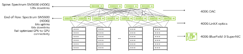
Figure 4: NVIDIA Spectrum-4 typical data center deployment structure (Source: NVIDIA)
Protocol and Traffic Control
- PFC: Allocate dedicated queues (e.g., queue 3) for RoCE traffic; enable deadlock prevention.
- ECN: Set port thresholds to mark packets and trigger congestion control.
- DCB: Use ETS to prioritize RoCE traffic.
- MTU: Set to 9214 bytes (Jumbo frames) to reduce fragmentation.
- Verify PFC/ECN coordination between switches and adapters.
- Certify third-party modules (e.g., AICPLIGHT 800G OSFP/QSFP-DD).
- Install latest drivers (e.g., NVIDIA MLNX-OFED) and firmware; test with iperf3/netperf (BER <1E-12, P90 latency <1μs).
4.Implementation Process: Standardized Operations
Follow a 4-step process for stable operation:
Acceptance: Parameter Verification
- Check packaging integrity; verify speed, wavelength, and distance match orders (e.g., QSFP-DD/OSFP 800G DR8, 1310nm, 500m).
- Use switch CLI to read DDM data (temperature, optical power, BER) and reject unqualified modules.
Link Connection and Initialization
- Physical Connection: Connect per topology; clean fiber endfaces with MPO tools.
- Link Training: InfiniBand switches auto-negotiate speed/width (verify via "ibstatus"); RoCE switches need "RoCE mode" and PFC/ECN enabled (check RDMA via "ethtool -K").
Function and Performance Testing
- Basic Connectivity: Test with ping (RoCE) or ibping (IB) for no packet loss.
- Throughput: IB uses "ib_write_bw" (≥90% line speed); RoCE uses "rdma_perftest" for zero-copy verification.
- Stress Testing: Simulate full load; monitor queue depth, temperature, and BER.
Long-Term Operation and Optimization
- Real-Time Monitoring: Deploy a network management system to track module status and link utilization.
- Fault Handling: Troubleshoot abnormal optical power (clean/replace) or high BER (signal/heat/firmware checks).
- Capacity Planning: Reserve 20% of ports/bandwidth for future cluster expansion.
5.Conclusion and Recommendations
Selection Recommendations- InfiniBand Networks: Prioritize NVIDIA-certified OSFP/QSFP112 modules (e.g., MMS4X00-NM) to ensure seamless compatibility with Quantum-2 switches and ConnectX adapter cards.
- RoCE Networks: Select QSFP-DD modules supporting the IEEE 802.3ck standard and match them with PFC/ECN configurations to achieve lossless transmission.
Technological Trends
- LPO/LRO Technology: Evaluate switch dynamic compensation.
- Liquid Cooling and CPO: Plan heat dissipation/power systems in advance for future high-bandwidth needs.
Risk Mitigation
Avoid mixing InfiniBand modules from different manufacturers. Prioritize NVIDIA LinkX or Mellanox-compatible solutions to reduce compatibility issues.
In RoCE networks, strictly configure PFC/ECN parameters and conduct regular traffic simulation tests to prevent deadlocks and congestion and ensure long-term stable network operation.
As intelligent computing centers demand higher bandwidth and lower latency, optical modules will evolve toward faster speeds, lower power consumption, and more compact form factors—becoming a key enabler for intelligent computing breakthroughs.
