 English
In data centers and fiber optic communication networks, the optical links between switches serve as the core channels for data transmission, and their stable connectivity directly determines the operational efficiency and reliability of the entire network. However, in actual deployment and operation and maintenance processes, optical link failures such as optical module docking failures and port Down often occur, which not only cause data transmission interruptions but may also affect business continuity. This article will elaborate on the core influencing factors, common causes, and targeted troubleshooting steps of optical link failures between switches, providing practical guidance for operation and maintenance personnel to quickly locate and solve problems.
Key Factors Affecting Optical Module Connection
In theory, connection is possible if the interface standard types are the same, but in actual use, attention should be paid to the range of transmitted and received optical power and the transmission distance. The main factors affecting the connection of optical modules are shown in following table.
| Factor | Description |
|---|---|
| Wavelength | It is forbidden to interconnect optical modules with different wavelengths. Due to different transmission loss and dispersion in optical fibers, the transmission distances corresponding to different wavelengths at the same rate are different. Therefore, optical modules with the same wavelength should be selected for interconnection. |
| Transmission Distance | Optical modules must match the actual application scenario. The interface indicators of optical modules with different distances differ greatly, and the price of long-distance optical modules is also high. Therefore, when interconnecting long-distance optical modules with short-distance optical modules, an optical attenuator must be added. To avoid burning the optical modules, it is recommended that the supported distance of the optical modules should not be less than the fiber length. |
| Data Rate | The nominal rate of the optical module must be consistent with the actual link rate. It is strictly prohibited to use low-rate optical modules to transmit high-speed signals. The nominal rate of the optical module must be greater than the interface rate. |
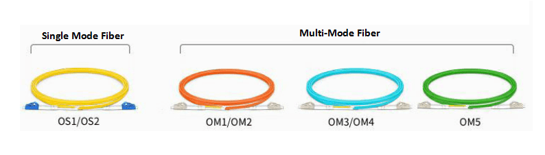
| Fiber Mode | Optical fibers and optical modules should be used in pairs, that is, single-mode optical modules use single-mode optical fibers, and multimode optical modules use multimode optical fibers. Do not mix them. |
Fault Phenomenon & Possible Causes
Two optical interfaces are connected through an optical fiber, but the local port is Down, and the optical modules fail to connect. Possible causes are listed below:
- The optical module used is not a switch-certified optical module.
- The optical module is incompatible with the optical fiber.
- The port is in shutdown state.
- The transmitted optical power is too low or too high.
- The received optical power is too low or too high.
- The optical modules connected at both ends are incompatible.
Step-by-Step Fault Handling
1.Verify Module Certification
Confirm whether the optical module on the Down port is a switch-certified one. For example, Huawei CE series switches should use Huawei data center switch-certified optical modules or the third-party compatible optical modules. Non-certified optical modules have unreliable performance and may cause the port to fail to go Up.
2.Check Fiber Compatibility
Confirm whether the optical module is compatible with the optical fiber.
- Single-mode optical modules (generally with wavelengths of 1310nm and 1550nm) correspond to single-mode optical fibers.
-
Multimode optical modules (generally with a wavelength of 850nm) correspond to multimode optical fibers.
3.Check Port Alarms & Status
Execute the command "display interface transceiver" to check whether there is any alarm information of the optical module under "Alarm information".
If a LOS Alarm is displayed, it indicates that no signal is sent from the opposite end. In the interface mode, execute the command "display this" to check whether the ports at both ends are shutdown. If the port is shutdown, execute the "undo shutdown" operation.
4.Diagnose Transmit/Receive Power
Execute the command "display interface transceiver verbose" to view the diagnostic information of the optical module and check whether there is any alarm information about the transmitted or received optical power of the optical module.
In the diagnostic information of the optical module, you can view the current transmitted and received optical power values, as well as the default maximum and minimum power values.
-
Low Receive Power (RxPower Low): If the received power is low (RxPower Low), it indicates that the signal received by the local end is too weak, which may cause the port to fail to go Up or packet loss during transmission and reception after going Up. At this time, first check whether the transmission distance is too far, exceeding the transmission distance of the opposite end's optical module, and then check whether the optical module or optical fiber is damaged.
-
High Receive Power (RxPower High): If the received power is high (RxPower High), it indicates that the signal received by the local end is too strong. The possible reason is that the opposite end's optical module is a long-distance optical module, but the actual transmission distance is too short, resulting in no signal attenuation. At this time, an optical attenuator should be added to the opposite end's optical module to protect the local end's optical module.
-
Low Transmit Power (TxPower Low): If the transmitted power is low (TxPower Low), it indicates that the local end's optical module has poor signal transmission or the optical module itself is faulty, which may cause the opposite end's received power to be low, resulting in the port failing to go Up or packet loss during transmission and reception after going Up. Please contact technical support personnel.
-
High Transmit Power (TxPower High): If the transmitted power is high (TxPower High), it indicates that the signal sent by the local end's optical module is too strong, which may cause the opposite end's received power to be high, resulting in the opposite end's optical module being burned due to continuously high received power. The possible reason is that the local end's optical module is faulty. It is recommended to replace the optical module.
Note: After inserting the optical module into the port and successfully connecting it, it is necessary to check for alarm information about the transmitted or received optical power to avoid abnormal traffic or optical modules due to too low or too high power.
5. Cross-Test Hardware (If No Alarms But Port Remains Down)
If there are no alarms at both ends but the port still does not go Up, first capture the detailed information and logs of the optical module, then try to replace the optical fiber or optical module to see if it can go Up. If it can go Up, it indicates that the original optical fiber or optical module itself is faulty. Please replace it with a new optical fiber or optical module. If it still cannot go Up, please contact technical support personnel.
Summary
The troubleshooting of optical link failures between switches should follow the logic of "confirm compatibility → check configurations → test hardware performance" to accurately locate core issues such as wavelength mismatch, power abnormalities, and hardware damage. By standardizing optical module selection, ensuring the compatibility of optical modules and optical fibers, promptly investigating power alarms, and reasonably using optical attenuators, the incidence of failures can be significantly reduced. If the problem still cannot be solved after troubleshooting according to the above steps, it is recommended to retain complete fault logs and optical module diagnostic information to facilitate further analysis and handling by technical support personnel, ensuring the long-term stable operation of optical links.
