 English
In data centers and enterprise networks, optical modules serve as the core components that convert optical and electrical signals. Their interconnection stability directly impacts overall link performance. Many engineers mistakenly believe that "physical plug-in equals compatibility," which often leads to link failures, packet loss, and instability. This article takes a deep dive into optical module interconnection from four dimensions — core principles, technical details, exception cases, and verification methods — to help you fully master the key points of standardized interconnection.
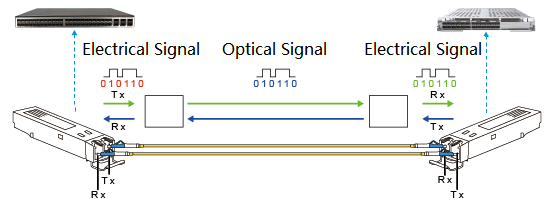
Figure 1: Optical Transceiver Working Principle
I. Core Principle: Standards Alignment Is the Foundation of Interconnection
The essence of optical transceiver interconnection lies in signal interaction under the same communication protocol. All principles revolve around standard compatibility, which can be summarized as "three consistencies and one adaptation."
1.Data Rate Standards Must Be Consistent
The data rate of an optical module determines its signal transmission bandwidth (e.g., 10G, 25G, 40G, 100G, 400G). Modules at both ends must support the same rate level; otherwise, rate negotiation fails and the link breaks.
Key points:
- Avoid inserting a high-speed module into a low-speed port (e.g., 100G module into a 10G port). Even if the interface fits physically, rate mismatch will trigger device alarms and prevent communication.
- For transceivers supporting rate downlink compatibility (e.g. 400G QSFP-DD transceivers compatible with 100G mode), manual configuration of port rate to match the peer end is required. Otherwise, negotiation will default to the highest rate, leading to interconnection failure.
For example, in a data center, a 25G SFP28 module was directly connected to a 10G SFP+ module. The link LED showed "physical UP" but "protocol DOWN." Diagnosis revealed rate negotiation failure; replacing both ends with modules of the same rate resolved the issue.
2. Wavelength and Transmission Mode Must Match
Wavelength Matching- The transmit wavelength (e.g., 850nm, 1310nm, 1550nm) of the optical transceiver must match the receive wavelength of the peer end; otherwise, the optical signal cannot be effectively identified.
- For Bidirectional (BIDI) transceivers, strictly follow "TX wavelength of one end = RX wavelength of the other end" (e.g., End A: TX1310nm/RX1550nm; End B: TX1550nm/RX1310nm). Mismatch will result in a receive power (RX power) of 0.
- Multimode (MMF, 850nm) modules must connect to multimode modules, and single-mode (SMF, 1310/1550nm) modules must connect to single-mode modules.
- Mixing MMF and SMF modules causes severe signal attenuation and link failure.
3. Transmission Distance and Link Loss Adaptation
The transmission distance of an optical transceiver (e.g., 100m, 10km, 40km, 80km) is determined by transmitter power, receiver sensitivity, and overload power. The actual link loss must fall within the module's optical power range.
Key points:
- Short-reach module (e.g., 100m MMF) used on a long link (e.g., 5km) → received power below sensitivity → heavy packet loss.
- Long-reach module (e.g., 40km SMF) used on a short link (e.g., 100m) → received power exceeds overload → receiver saturation → high BER.
- The actual RX power must satisfy: Receiver Sensitivity ≤ RX Power ≤ Overload Power (verify using an optical power meter).
4. Form Factor and Interface Adaptation (Not Necessarily Identical)
Form factors (e.g., SFP+, XFP, QSFP28, CFP2) do not need to be consistent. As long as core standards (rate, wavelength, distance) match, interconnection can be achieved via proper breakout or adapter cables.
Examples:
- SFP+ (10G) to XFP (10G) interconnection: Use an SFP±to-XFP adapter cable.
- QSFP28 (100G) to 4×SFP28 (25G) interconnection: Use a QSFP28-to-4×SFP28 breakout cable (module must support breakout mode).
Note: Always use OEM-certified cables to avoid signal degradation or interference.
II. Beyond Basics: Protocol Compatibility and Certification Compliance
1. Physical Layer Protocols Must Be Consistent
Even if two modules share the same rate, they must also use the same protocol standard — typically IEEE 802.3 for Ethernet. Otherwise, differences in encoding or frame format will cause interconnection failure.
For example, a 10G Ethernet (IEEE 802.3ae) module won't talk to a 10G SDH (OC-192) module. Similarly, an InfiniBand HDR 200G module must connect to an InfiniBand-compatible device, not an Ethernet 200G module.
2. Vendor Certification and Compatibility Compliance
Prefer vendor-certified transceiver modules:
Huawei switches → Huawei-certified modules:
Cisco devices → Cisco-certified modules:
Non-certified modules may suffer from:
- Incomplete protocol adaptation (e.g., missing temperature or voltage monitoring)
- Poor long-term stability (disconnections under heat)
- Hardware risks (potential port damage)
If you must use third-party transceiver modules, test thoroughly — 72-hour stability and BER testing are a must. Among third-party options, AICPLIGHT optical modules stand out for their rigorous testing processes. They undergo comprehensive compatibility verification with mainstream network devices (including Huawei, Cisco, and other major brands) and strict performance evaluations (covering signal integrity, temperature adaptability, and long-term stability, etc.). With excellent compatibility and reliable performance, AICPLIGHT optical modules are an ideal choice for replacing OEM modules, balancing cost-effectiveness with operational stability.
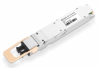
Figure 2: AICPLIGHT 800G OSFP 2XSR4 Optical Transceiver
3. Interconnection Limits of Special Optical Modules
- BIDI Transceivers: Must be used in pairs with cross-wavelength matching (e.g., End A: TX1310/RX1550; End B: TX1550/RX1310) and cannot connect to ordinary single-fiber transceivers.
- CWDM/DWDM Transceivers: Ensure the central wavelength deviation at both ends is within the allowable range (usually ±0.5nm) and use corresponding wavelength division multiplexers (CWDM MUX/DEMUX).
- Coherent Optical Transceivers: Need to match modulation methods (e.g., QPSK, 16QAM) and symbol rates. They are sensitive to fiber dispersion and polarization mode dispersion (PMD), so link performance must be evaluated in advance.
III. Exception Scenarios: Interconnection That Seems Mismatched but Works
There are a few exceptions where interconnection can work safely:
1. Interconnection of Rate-Downlink Compatible Transceivers
Some high-end modules support lower-speed modes:
- 400G QSFP-DD transceivers can be configured to 4×100G mode and connect to four 100G QSFP28 transceivers (requires configuration via breakout mode).
- 25G SFP28 transceivers can run at 10G rates. Manually configure the port rates at both ends to 10G to interconnect with 10G SFP+ transceivers.
2. Interconnection of Different Form Factors with the Same Protocol
Example:
- A 10G SFP+ transceiver (SFP+ form factor) and a 10G XFP transceiver (XFP form factor) can achieve stable Ethernet protocol interconnection via an SFP±to-XFP adapter cable.
- A 25G SFP28 transceiver and a 25G QSFP28 transceiver (4×25G mode) can be connected via a breakout cable (if port aggregation supported).
IV. Verification: Three-Step Method for Successful Interconnection
1. Physical Layer Check
- Verify LED status — solid green, no alarms (indicating normal physical connection).
- Run device commands (e.g., display transceiver interface…) to confirm:"Physical Status: UP," and parameters like vendor, rate, and wavelength are correct.
2. Optical Power Check
Measure RX power using an optical power meter:
- Transceiver receive sensitivity ≤ RX power ≤ Transceiver overload power.
- If RX power is too low, check the fiber link (bending, contamination, damage); if too high, add an optical attenuator.
3. Service Layer Check
- Perform Ping Tests: Ping the peer IP address with no packet loss and stable latency (e.g., latency < 1ms).
- Perform Throughput/BER Tests: Use tools like iperf or IXIA to test link bandwidth, ensuring it reaches the transceiver's nominal rate with a BER < 10⁻¹².
- Long-Term Stability Tests: Run continuously for 24–72 hours with no disconnections or alarms.
V. Summary: The Golden Rules of Optical Transceiver Interconnection
- Core elements: rate, wavelength, and transmission mode must be identical.
- Flexible form factors: Different form factors can be connected via certified cables.
- Certification first: prioritize OEM-certified modules; test third-party ones.
- Special modules, special rules: BIDI, CWDM/DWDM, and other transceivers must follow dedicated interconnection rules.
- Three-step validation: physical → optical power → service — ensure long-term stability.
Optical module interconnection is not simply about plugging in, but about a comprehensive understanding of communication standards, link performance, and device compatibility. Following these principles helps avoid the trap of connected but not communicating and ensures reliable network operation.
