 English
Cabling design must align with transceiver selection, especially in 800G vs 1.6T network architectures.As AI clusters rapidly scale from 400G toward 800G network architectures, most discussions focus on switch ASICs and high-speed optical transceivers. In real-world deployments, however, the stability and performance of parallel optical links are often determined by the MPO/MTP cabling infrastructure.
In 400G and 800G AI data center networks, MPO/MTP cabling is not just a passive component. It directly impacts link stability, lane mapping, and achievable reach. Choosing the wrong fiber type, polarity, or connector configuration can prevent links from coming up—even when high-end optical transceivers are used. This guide explains how to properly design and deploy MPO/MTP fiber cable for 400G and 800G parallel optics, helping ensure predictable performance and long-term scalability.
Choosing the Correct Fiber Type for 400G and 800G Optics
For 400G and 800G parallel optics, fiber type must match the transceiver's reach and wavelength. SR modules require multimode fiber, while DR modules require single-mode fiber. Using the wrong fiber type typically results in reduced reach, unstable links, or complete signal failure.
Multimode Fiber (MMF): Short-reach optical modules such as 400G SR8, 400G SR4, and 800G SR8 require multimode fiber. OM4 is widely deployed today and fully supports most 400G and 800G SR applications. OM5, with extended wavelength support, offers additional future-proofing for short-wavelength multiplexing scenarios and may be considered in new builds targeting longer upgrade cycles.
Single-Mode Fiber (SMF): Mid-reach modules including 400G DR4 and 800G DR8 / 2×DR4 require single-mode fiber. For these links, OS2 fiber compliant with ITU-T G.652.D (zero water peak) is the industry-standard choice, ensuring low attenuation and consistent performance.
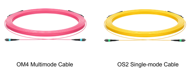
Figure 1: MPO fiber cable - OM4 multimode fiber cable and OS2 single-mode fiber cable
Matching Fiber Count and MPO Interface to Parallel Optics
Parallel optics rely on multiple transmit and receive lanes operating simultaneously. Correct fiber count and MPO interface selection are essential for proper lane mapping.
8-Channel Optical Modules (SR8/DR8): These transceivers use eight transmit and eight receive lanes, requiring 16 fibers in total.
-
400G QSFP-DD SR8 modules typically use MPO-16 connectors.
-
800G OSFP SR8 modules may use either a single MPO-16 connector, or dual MPO-12 connectors.
For example, the AICPLIGHT 800G OSFP 2×SR4 / SR8 optical transceiver uses dual MPO-12 connectors and supports transmission distances of up to 50 meters over OM4 multimode fiber.
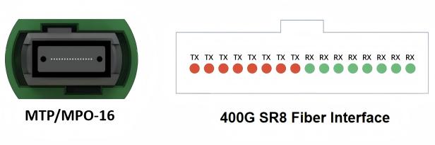
Figure 2: 400G SR8 fiber interface - MTP/MPO-16 connector
4-Channel Optical Modules (SR4/DR4): These modules use four transmit and four receive lanes, requiring 8 fibers. Devices such as 400G QSFP-DD SR4 or DR4 typically use MPO-12 connectors, with the four center fibers left unused.
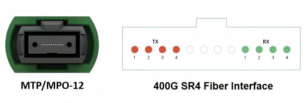
Figure 3: 400G SR4 fiber interface - MTP/MPO-12 connector
Any mismatch between fiber count and transceiver interface can lead to lane alignment errors and link failures.
MPO/MTP Polarity: Why Type-B Is the Preferred Choice
Polarity defines how transmit lanes at one end connect to receive lanes at the other. Incorrect polarity prevents the optical signal from reaching the receiver, even if all components are otherwise compatible.
MPO/MTP standards define three polarity types:
-
Type-A: Straight-through mapping.
-
Type-B: Fully reversed mapping.
-
Type-C: Pair-flipped mapping.
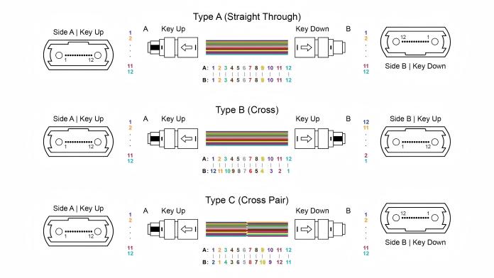
Figure 4: MPO Polarity - Type A (straight through), Type B (fully reversed), Type C (Pair flipped)
For direct module-to-module connections in 400G and 800G parallel optics, Type-B polarity is the most widely adopted and recommended option. It simplifies deployment, reduces configuration risk, and aligns with most modern transceiver designs.
AICPLIGHT recommends Type-B polarity for the majority of AI data center interconnect scenarios.
Planning Cable Length and Breakout Configurations
Physical layout and network architecture directly influence cabling requirements in AI clusters.
Cable Length Optimization: Patch cables should closely match actual routing distances. Excess slack increases optical attenuation and can obstruct airflow in high-density racks, negatively affecting thermal performance.
Breakout Cabling in AI Clusters: A common AI data center scenario is breaking one 800G switch port into two independent 400G links. This is typically achieved using MPO-16 to dual MPO-12 breakout cables or dual MPO-12 connections, depending on the transceiver interface.
-
If the 800G module uses a single MPO-16 connector, an MPO-16 to dual MPO-12 breakout cable is required.
-
If the 800G module uses dual MPO-12 connectors, two independent MPO-12 patch cables should be used.
For example, an 800G OSFP 2×DR4 module on the switch side can be connected via two MPO-12 fiber cables. On the server side, each link terminates at a 400G OSFP or QSFP112 DR4 module installed in NVIDIA ConnectX-7 network adapters.
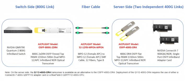
Figure 5: 800G link breaking into two independent 400G links
Proper breakout design ensures efficient bandwidth utilization and simplifies future network scaling.
Connector Gender and End-Face Type Considerations
Physical connector compatibility is the final checkpoint before deployment.
Connector Gender: Optical transceivers typically use male MPO connectors (with guide pins). Therefore, patch cables must be equipped with female MPO connectors (with guide holes). A mismatch prevents physical connection.
End-Face Polishing: APC vs. UPC - Modern 400G and 800G parallel optical modules require APC (Angled Physical Contact) connectors. The angled end face reduces back reflection, which is especially critical in multi-lane parallel optics.
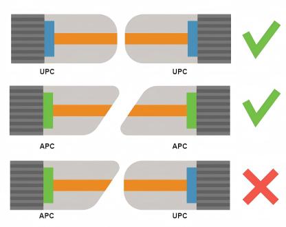
Figure 6: UPC and APC connection rules
Critical Safety Note: APC and UPC MPO connectors must never be mated together. Mixing these connectors causes severe optical performance degradation and can permanently damage transceivers and fiber end faces.
Conclusion
In 400G and 800G AI data center networks, MPO/MTP cabling plays a critical role in link stability and performance. Choosing the correct fiber type, polarity, and connector configuration ensures reliable parallel optics and prevents common deployment failures.
Optical transceivers define theoretical bandwidth but MPO/MTP cabling determines whether that bandwidth can be delivered reliably in production. By validating fiber type, fiber count, polarity, and connector specifications upfront, operators can eliminate many of the hidden risks that cause deployment delays and link instability.To avoid failures, read our multimode Y-cable compatibility guide. At AICPLIGHT, we approach optical interconnects as a complete system. Our transceivers and MPO/MTP cabling solutions are validated together to support stable, scalable, and future-ready 400G and 800G parallel optics infrastructures for modern AI data centers.
