 English
Introduction
1. BER of Optical Module
1.1 What is BER?
1.2 How BER Occurs
-
Transmitter Side: Laser devices generate optical signals carrying digital data.
-
Fiber Transmission: Signal distortion occurs due to medium properties and environmental factors.
-
Receiver Side: Coherent detection modules convert signals back to electrical form but introduce noise.
Primary BER Contributors in 400G Coherent Links:
-
Optical Module Factors: Device aging, improper parameter configuration.
-
Fiber Link Factors: Fiber attenuation, connector contamination, or end-face scratches.
-
External Environmental Factors: Electromagnetic interference, extreme temperature fluctuations.
2. BER Testing and Validation for 400G Links
2.1 Real-Time Monitoring Metrics and Test Tools for Coherent Links
-
OSNR (Optical Signal-to-Noise Ratio): Directly reflects signal-noise separation and is a key determinant of BER.
-
Optical Power: Must be maintained within the module's operational threshold to avoid distortion from over/under-power conditions.
-
Dispersion Accumulation: Excessive chromatic dispersion degrades signal integrity.
-
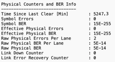
FEC (Forward Error Correction) Counts: Indicates the frequency of error corrections, indirectly revealing BER trends.
-
Coherent Optical Performance Analyzer: Measures OSNR, modulation quality, and phase noise.
-
High-Speed Bit Error Rate Tester (BERT): Validates BER performance under stress conditions.
-
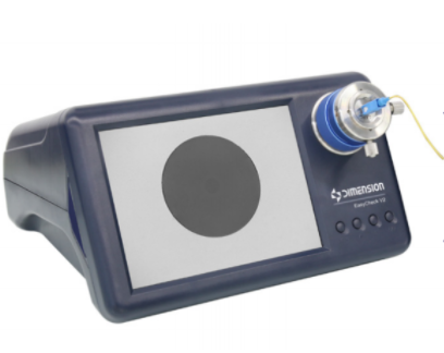
Optical Time-Domain Reflectometer (OTDR): Locates fiber faults, splice losses, and attenuation spikes.
-
Optical Spectrum Analyzer (OSA): Assesses wavelength stability and noise levels.
2.2 Complete Fiber Link Testing Procedure
Step 1: Link Pre-Treatment
-
Clean fiber connector end-faces to eliminate contamination.
-
Verify connector insertion loss and physical integrity.
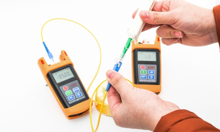
Step 2: Optical Power Validation
-
Measure Tx (transmitter) output power and Rx (receiver) input power.
-
Calculate total link attenuation to ensure compliance with budget.
Step 3: Dispersion and PMD Testing
-
Use a dispersion analyzer to quantify chromatic dispersion accumulation.
-
Confirm values are within the module's compensation range (e.g., DSP-based correction).
Step 4: OTDR Trace Analysis
-
Map attenuation distribution along the fiber span.
-
Identify localized losses at splices, connectors, or bends.
Step 5: BER Validation
-
Conduct prolonged BER tests under operational conditions (e.g., 24+ hours).
-
Correlate results with FEC counts and module health indicators.
3. BER Optimization for 400G Long-Haul Links
3.1 FEC Technology
3.2 Environmental and Operational Impacts
Environmental Controls:
-
Temperature Stability: Maintain ambient temperature at 10–35°C to prevent laser threshold drift and fiber property changes. Deploy active thermal management systems.
-
EMI Shielding: Isolate optical modules ≥30 cm from power cables/radio devices; use shielded fiber jumpers to suppress noise.
Operational Practices:
-
Fiber Maintenance: Regularly clean connectors with specialized tools to avoid contamination/scratches causing reflection loss.
-
Process Compliance: Enforce standardized module handling (e.g., gentle insertion) and automated configuration checks to prevent signal degradation.
3.3 External Link Loss Compensation
Attenuation Mitigation:
-
EDFA (Erbium-Doped Fiber Amplifier): Compensates for power loss, ensuring received optical power stays within the module's sensitivity range.
-
Distributed Amplification: Prevents nonlinear distortions from concentrated amplification (e.g., Raman amplification combined with EDFA).
Dispersion Management:
-
Dispersion-Compensating Fiber (DCF) or Tunable Dispersion Compensators: Align cumulative dispersion with the DSP's correction capability.
-
Proactive Monitoring: Track performance of compensation devices and replace aged components (e.g., degraded EDFA pumps).
