
 English
How do you scale your network from 400G to 800G—without replacing your entire infrastructure? This is the exact challenge many AI data centers are facing today. As GPU clusters grow and east-west traffic explodes, simply adding more 400G ports is no longer efficient—either in cost, power, or density.
The answer? 800G to 400G breakout. It has emerged as a smarter alternative—allowing network operators to aggregate multiple 400G links using fewer high-speed ports, while maintaining flexibility and future scalability. This article provides a deep dive into the technical mechanisms, hardware requirements, and economic benefits of using 800G ports to power 400G networks.
What is 800G Breakout?
At its core, a "Breakout" configuration involves taking a single high-bandwidth physical port on a switch—in this case, 800Gbps—and splitting it into multiple lower-bandwidth logical ports (e.g., 2x 400G).
To comprehend how 800G breakout functions, one must first look at the underlying electrical lane architecture of optical transceivers. Whether housed in an OSFP or QSFP-DD form factor, an 800G optical module operates on an eight-lane electrical interface. In earlier 400G systems, these eight lanes typically operated at 50Gbps each. However, the move to 800G is defined by the transition to 112G SerDes technology, where each of the eight electrical lanes carries 100Gbps using PAM4 modulation.
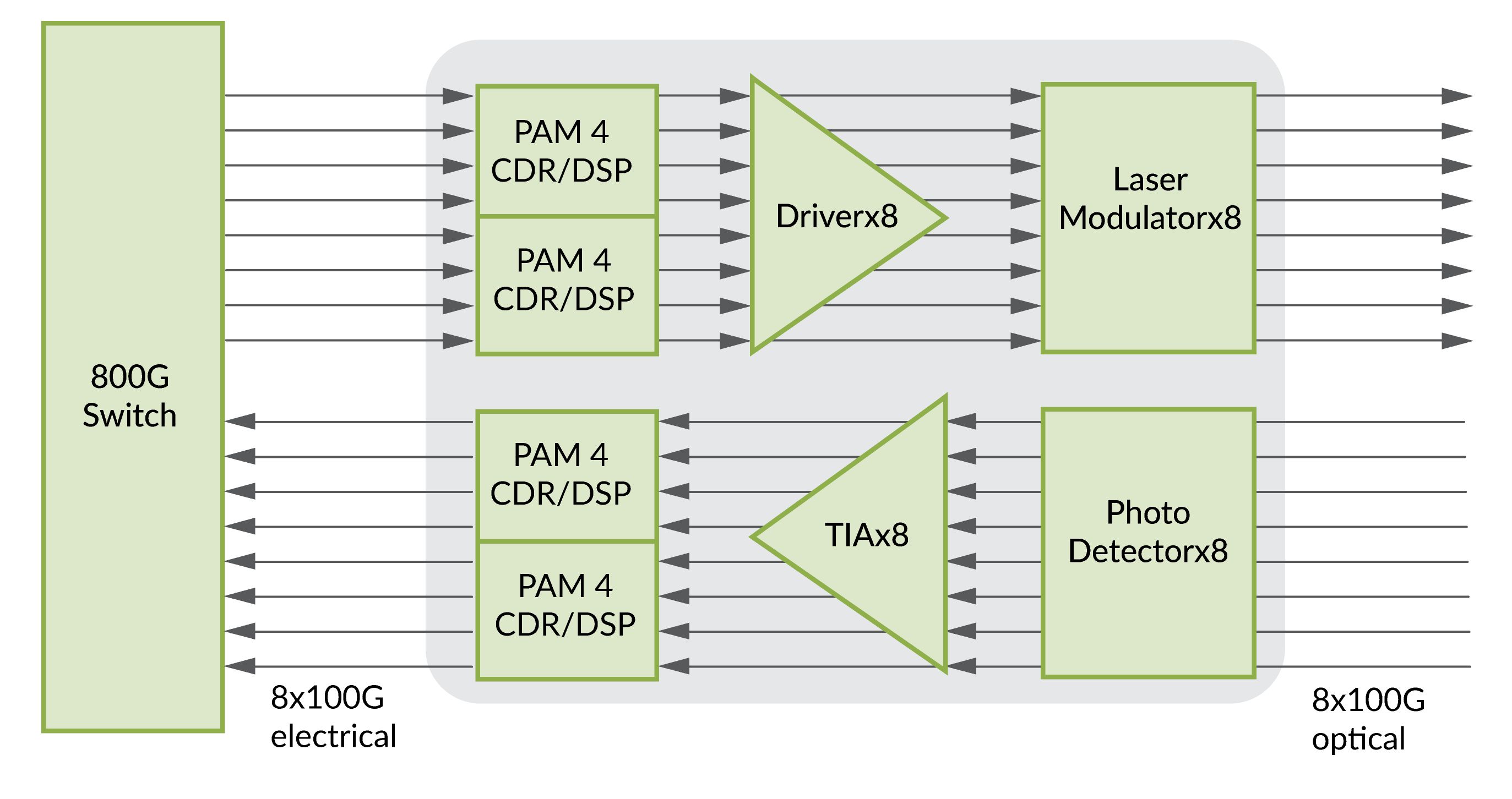
Figure 1: This block diagram illustrates the internal architecture of an 800G optical transceiver, featuring 8x100G PAM4 electrical lanes converted into 8x100G optical signals through high-performance DSP/CDR, Driver, and Laser Modulator components.
This shift is what truly enables the breakout capability. By configuring the switch's network operating system (NOS), these eight lanes can be logically partitioned into two independent groups of four lanes. This effectively transforms a single high-bandwidth 800G port into two physically distinct 400G logical interfaces, allowing a high-tier spine switch to communicate directly with multiple leaf switches or high-performance servers without requiring intermediate conversion hardware.
800G to 400G Breakout Compatibility: 100G PAM4 Modulation
One of the most vital aspects of implementing a successful 800G to 400G breakout strategy lies in the synchronization of modulation schemes across the entire link.
There is a common misconception that any 800G port can seamlessly break out to any 400G module. In reality, the 800G port is natively designed for 100G per-lane modulation (100G PAM4). Therefore, the recipient 400G modules must also be based on 100G-per-lane technology, such as the 400G DR4. If an operator attempts to connect an 800G breakout link to an older 400G SR8 module—which relies on 50G PAM4—the link will fail to initialize unless the hardware incorporates an expensive and power-hungry gearbox chip.

Figure 2: This image illustrates an 800G to 2×400G breakout solution using PAM4 modulation at 100G per lane, connecting a Mellanox MQM9700 switch to an H100 server via an OSFP-800G-2DR4 module split into two OSFP-400G-DR4 transceivers over MPO fiber cables.
This technical alignment is the "invisible" hurdle in link aggregation; for a breakout to be truly efficient, the entire ecosystem must speak the same 100G-per-lane language. This ensures that the signal passes through the fiber with minimal latency and maximum integrity, which is essential for the strict timing requirements of AI training workloads.
800G to 400G Breakout Implementation Paths
The physical execution of 400G aggregation through 800G ports offers several distinct paths, each tailored to specific data center distances.
"Twin Engine" Solution
For medium-range reach, such as 2km connections between rows, the 800G-2xFR4 module has become the preferred choice. This "twin-engine" design is remarkable because it integrates two completely independent 400G optical engines within a single transceiver housing. Instead of using a complex splitter cable, the module features two standard LC Duplex connectors on its faceplate. This allows engineers to use traditional, inexpensive fiber patches to connect to two different 400G devices, greatly simplifying cable management in high-density environments.
MPO Parallel Breakout
In contrast, for shorter-range applications within a single rack or across adjacent racks, the industry relies heavily on MPO-based breakout cables or Direct Attach Copper (DAC) solutions. The 800G-DR8 module, for instance, utilizes a single MPO-16 interface that carries eight pairs of fiber. Through the use of a "Hydra" breakout cable, these sixteen fibers are physically split into two MPO-8 connectors at the far end. This method is particularly effective for connecting a 800G top-of-rack switch to multiple GPU-heavy servers equipped with 400G NICs.
Copper-Based Breakout (DAC)
For the absolute shortest distances, 800G to 2x 400G DAC breakout cables offer a zero-power alternative, utilizing passive copper shielding to maintain signal quality while eliminating the electricity costs associated with optical lasers.

Figure 3: This image demonstrates an 800G to 2x400G OSFP Passive Direct Attach Copper (DAC) breakout connection, linking a Mellanox MQM9700 switch to an H100 server via two ConnectX-7 network cards.
Tech Tip: When implementing MPO parallel breakout, engineers must account for the Optical Link Loss Budget. Breakout architectures often introduce additional connection points, such as Hydra cables or cassette transitions, which add incremental insertion loss. Since 100G PAM4 signaling is more sensitive to noise, excessive loss exceeding 1.5dB - 2.0dB can lead to an increased Bit Error Rate (BER), necessitating a reduction in maximum reach. For instance, a 500m DR4 link may need to be derated to under 400m in complex breakout environments to maintain signal integrity during peak AI workloads.
Benefits of 800G to 400G Breakout
The shift toward 800G breakout aggregation is driven as much by economics as it is by engineering necessity. When analyzing the Total Cost of Ownership, the efficiency of 800G becomes clear. Purchasing a single 800G transceiver is significantly more cost-effective than purchasing two separate 400G transceivers, often resulting in a 20% to 30% reduction in capital expenditure per gigabit.
Furthermore, the power efficiency gains are substantial. A typical 800G module consumes between 16W and 18W, whereas two equivalent 400G modules would combined consume roughly 24W. When multiplied by thousands of ports in a large-scale data center, this reduction in power consumption leads to massive savings in both electricity bills and the operational costs associated with thermal management and cooling infrastructure.
Moreover, the density advantage cannot be overstated. A standard 1RU switch chassis that supports 32 ports of 800G can effectively host 64 links of 400G through breakout configurations. This doubles the network's capacity without requiring additional rack space, floor space, or expensive real estate within the data center. It allows operators to delay expensive facility expansions while still meeting the explosive bandwidth demands of their users. By aggregating 400G links into 800G ports, organizations are essentially future-proofing their investments. When the time comes to transition the entire network to 800G, the underlying switch infrastructure is already in place, requiring only a simple cable replacement and software reconfiguration rather than a complete hardware overhaul.
Strategic Considerations for High-Performance Deployment
While the benefits of 800G breakout are compelling, successful deployment requires meticulous planning regarding thermal dynamics and software management. 800G modules generate significant heat, and the choice of form factor plays a major role in long-term reliability. The OSFP form factor, with its integrated cooling fins, is often favored for these high-power applications because it can maintain a operating temperature several degrees lower than the QSFP-DD, which relies on the switch's internal airflow. Additionally, network administrators must ensure their Network Operating System (NOS) supports granular port-splitting commands. The ability to monitor each 400G logical link independently within a single 800G physical port is crucial for troubleshooting and maintaining the high availability required by modern enterprise applications.
Conclusion
In conclusion, the 800G Breakout solution represents a fundamental evolution in how we conceive of network scalability. It bridges the gap between generations of technology, allowing for a seamless aggregation of 400G links that is both high-performance and cost-aware. By leveraging 100G PAM4 modulation and choosing the appropriate physical cabling strategy, data center operators can build a resilient, high-density network that is ready for the challenges of the AI-driven future. As the industry continues to innovate, the lessons learned from 800G aggregation will undoubtedly pave the way for the next great leap into 1.6T networking.


