 English
Introduction
The TIA-568 standard serves as the technical cornerstone of fiber optic structured cabling, and its specifications for polarity directly determine the integrity and reliability of optical signal transmission. In high-density network environments, the widespread application of MPO/MTP connectors has significantly increased the complexity of polarity management. The rational selection among Type A/B/C polarity schemes has become critical for ensuring link performance. This article will provide a detailed analysis of this topic to facilitate users in selecting appropriate fiber optic solutions.
1. TIA-568 Fiber Optic Cabling Standard
1.1 TIA-568 Standard System and Fiber Optic Cabling Specifications
The TIA-568 standard is the core technical specification for structured cabling systems in North America. Developed and continuously updated by TIA, it has undergone three major version iterations—A, B, and C—gradually refining the technical requirements for fiber optic cabling. This standard system provides clear definitions regarding link structure, connector types, and transmission performance dimensions, covering both single-mode and multi-mode fiber applications, and adapting to high-density cabling environments such as data centers and enterprise campuses.
The specifications clearly define the subsystem division of structured cabling, requiring fiber optic links to follow the cabling topology of horizontal and backbone subsystems. It also establishes a basic framework for polarity management to ensure precise correspondence between the optical signal transmitter and receiver. Additionally, the fiber optic cabling specifications include key indicators such as link length limitations and bend radius requirements, providing unified technical criteria for the design, construction, and acceptance of cabling projects.
1.2 Core Cabling Rules of TIA-568-C Standard
The TIA-568-C standard represents a significant update to this framework. Its TIA-568-C.3 substandard specifically establishes core rules for fiber optic cabling, offering strong practical guidance. These rules explicitly define termination consistency requirements for fiber optic links, mandating that connector terminations maintain core sequence correspondence to eliminate polarity reversal risks at the source.
Regarding cabling topology, the standard emphasizes the preferred use of star topologies and requires separate routing of fiber optic and copper links to minimize electromagnetic interference affecting optical signal transmission. For high-density cabling scenarios, the rules add adaptation specifications for MPO/MTP connectors, clearly defining their application standards in backbone subsystems. Meanwhile, it establishes testing methods and qualification thresholds for performance parameters such as link attenuation and insertion loss. Furthermore, the rules strengthen compatibility requirements for cabling systems, ensuring seamless integration between newly deployed links and existing infrastructure to improve flexibility and cost-effectiveness in network expansion.
2. MPO/MTP Fiber Optic Polarity Analysis
2.1 Differences Between Type A, B, and C
The core distinctions among the Type A, B, and C MPO/MTP fiber polarity schemes lie in the core mapping relationships and keyed orientation configurations during connector termination. All must adhere to the polarity management requirements of the TIA-568 standard.
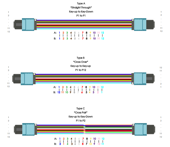
Type A: Features identical keyed orientations on both connectors, with cores sequentially mapped 1-12. Signal paths remain uncrossed and uninverted, making it suitable for basic bidirectional transmission scenarios.
Type B: Requires flipping one connector's key orientation by 180°, reversing the fiber core mapping sequence. Specifically, core 1 at End 1 corresponds to core 12 at End 2, forming a cross-linked unidirectional transmission path.
Type C: Implementation crosses fibers internally within the connector, where core 1 at End 1 corresponds to core 2 at End 2, core 2 at End 1 corresponds to core 1 at End 2, and so on. This configuration supports high-density requirements for duplex transmission.
2.2 Polarity Schemes for Different Applications
According to the TIA-568 standard, Type A, B, and C polarity schemes are designed for different fiber optic cabling scenarios.
Type A:
-
Advantage: Simple link structure and easy polarity verification.
-
Application: Primarily used in point-to-point backbone connections within data centers and short-distance fiber transmission in enterprise campus networks.
Type B:
-
Advantage: Features unidirectional cross-connect transmission, making it suitable for branch-to-trunk connections.
-
Application: Enables multi-channel signal splitting via a single MPO patch cord, reducing cabling complexity in distributed networks.
Type C:
-
Advantage: Optimized for high-density duplex transmission.
-
Application: Ideal for high-speed interconnections between servers and switches in data centers, minimizing patch cord usage and improving rack space efficiency.
All three schemes require proper MTP-MTP cable selection to ensure polarity alignment with equipment port requirements.
3. Analysis of Fiber Polarity Reversal Fault Causes
Fiber polarity reversal is a common issue affecting link transmission stability, primarily caused by deviations from TIA-568 standard compliance.
3.1 Termination Errors
Incorrect fiber core mapping during installation, violating Type A/B/C configuration rules, leading to mismatched Tx/Rx connections.
3.2 MPO/MTP Keying Misalignment
For Type B, one connector must be rotated 180°; identical keying on both ends directly causes polarity reversal.
3.3 Incorrect MTP-MTP Cable Selection
Mixing crossover and straight-through cables without aligning with the intended polarity scheme.Device Port Polarity Mismatch.
Additionally, incompatible polarity presets between device ports and cabling links, coupled with the absence of compliance verification testing, can create latent polarity faults. These ultimately cause transmission issues like signal interruptions and increased bit error rates. Therefore, fiber polarity selection must align with the deployed solution.
