As AI workloads continue to scale, many data centers are adopting 800G Ethernet at the switch layer while retaining 400G connectivity at the server layer. This has made 800G to 2×400G breakout architectures a common and practical design choice for modern AI clusters.
In AI data centers, an 800G to 2×400G breakout architecture allows a single 800G switch port to be split into two independent 400G links. This is commonly achieved using MPO breakout cabling, depending on whether the optical module exposes a single MPO-16 or dual MPO-12 interfaces. This article explains how to cable an 800G port into two independent 400G links using
MPO breakout cables, with practical guidance for AI data center environments.
Why 800G to 2×400G Breakout Is Common in AI Clusters
In GPU-based AI clusters, network architectures often evolve in stages:
-
Switches adopt 800G ports to maximize fabric bandwidth
-
Servers and NICs continue to operate at 400G for cost, power, and compatibility reasons
Breaking a single 800G switch port into two independent 400G links allows operators to:
-
Increase port utilization
-
Maintain compatibility with existing 400G servers
-
Scale bandwidth without a full infrastructure replacement
This approach is especially common in leaf–spine architectures connecting 800G switches to GPU servers.
Understanding 800G Optical Module Interfaces
Before selecting breakout cabling, it is critical to understand how 800G optical modules expose their lanes.
Some 800G modules, such as 800GBASE-SR8 QSFP-DD optical transceiver use a single MPO-16 connector, carrying eight transmit and eight receive lanes in one interface. In breakout scenarios, this design requires: One MPO-16 to dual MPO-12 breakout cable.
Many 800G OSFP modules—especially 2×DR4 or 2×SR4 designs—use two independent MPO-12 connectors, with each connector carrying one 400G link. In this case, no breakout cable is required. Two standard MPO-12 patch cables are used.
Understanding which interface your transceiver provides is the first step in selecting the correct cabling solution.
MPO Breakout Cabling Options for 800G to 2×400G
Option 1: MPO-16 to Dual MPO-12 Breakout Cable
This option is used when the 800G module exposes a single MPO-16 interface.
This approach allows a single 800G port to be logically split into two independent 400G connections.
Option 2: Dual MPO-12 Direct Connections
When the 800G module uses dual MPO-12 connectors, breakout cabling is not required.
This design simplifies cabling and reduces the risk of polarity or fiber-mapping errors.
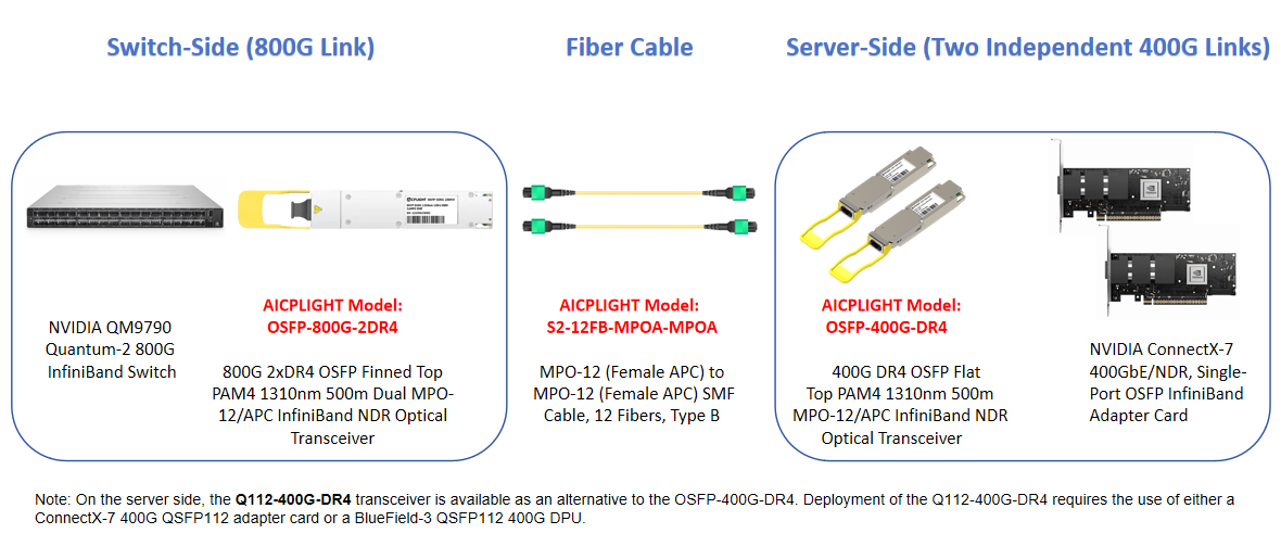
Example Deployment: 800G Switch to 400G GPU Servers
A typical AI cluster deployment may look like this:
-
Switch side: 800G OSFP 2×DR4 optical module
-
Cabling: Two MPO-12 fiber patch cables
-
Server side: 400G OSFP DR4 or QSFP112 DR4 modules installed in NVIDIA ConnectX-7 adapters
In this configuration, the original 800G port is logically divided into two independent 400G links, each connecting to a separate GPU server or NIC port. This architecture provides high bandwidth efficiency while preserving operational simplicity.
MPO Polarity Considerations in Breakout Scenarios
Polarity errors are one of the most common causes of breakout link failures.
For most 800G to 2×400G MPO breakout deployments: Type-B polarity is recommended.
It ensures correct transmit-to-receive lane alignment across both links.
Using inconsistent polarity across breakout cables can result in one link coming up while the other fails, making troubleshooting more complex.
Common MPO Breakout Cabling Mistakes
Even with the correct optical modules, cabling mistakes can prevent successful deployment.
- Using the Wrong Connector Type
Attempting to use MPO-12 cables with a single MPO-16 800G module without a proper breakout assembly will result in incompatible lane mapping.
- Incorrect Connector Gender
Optical modules typically use male MPO connectors. Patch cables must be female. A mismatch prevents physical connection.
- Mixing APC and UPC End Faces
APC and UPC MPO connectors must never be mated together. Mixing them can cause severe signal degradation and permanent hardware damage.
- Poor Cable Length Planning
Excess slack increases attenuation and disrupts airflow in dense AI racks, negatively affecting thermal performance.
Best Practices for Reliable 800G Breakout Deployment
To ensure stable and scalable breakout links:
-
Verify the optical module interface (MPO-16 vs dual MPO-12)
-
Use Type-B polarity consistently across the link
-
Match connector gender correctly
-
Avoid mixing APC and UPC connectors
-
Validate breakout configurations before large-scale rollout
Following these practices significantly reduces deployment risk and simplifies future expansion.
Conclusion
Breaking an 800G port into two 400G links is a practical and widely adopted approach in AI data centers. While optical transceivers enable this flexibility, MPO breakout cabling is what determines whether the design works reliably in production. By selecting the correct MPO interface, breakout method, and polarity scheme, operators can build scalable AI clusters that balance performance, cost, and operational simplicity.
For a complete system view, refer to 400G/800G cabling guide. At AICPLIGHT, we validate 800G and 400G optical modules together with MPO breakout cabling to ensure predictable performance in real-world AI data center deployments.
 English