English
Introduction
1. PAM4 Technology
1.1 What is PAM4?
Key Features:
-
Gray Code Mapping: Reduces bit error rates during signal transitions.
-
Multi-Level Signal Waveform: Requires sophisticated signal processing for accurate demodulation.
-
Standardized for High-Speed Networks: Adopted in IEEE 802.3 for 400GE, 200GE, and beyond, making it critical for data centers and 5G transport networks.
1.2 Advantages of PAM4
-
Doubled Bandwidth Efficiency: Achieves 2x the bit rate at the same baud rate, reducing channel bandwidth requirements by 50% and minimizing signal loss.
-
Cost-Effective Deployment: Leverages existing fiber infrastructure and optical components, significantly reducing hardware investment in network construction and upgrades. PAM4 demonstrates superior signal-to-noise ratio (SNR) performance over long distances. Combined with optimized equalization techniques, it achieves low bit error rates (BER) for reliable high-speed transmission.
-
Future-Proof Scalability: Enables smooth transitions from 100G → 400G → 800G/1.6T without overhauling network architecture.
2.Comparisons of PAM4 in 100G & 400G Ethernet
2.1 PAM4 in 100G Ethernet
Key applications: 2.1.1 Data Center Short-Distance Interconnects (100G BASE-KP4)
-
Uses 13.6 GBaud PAM4 to achieve 50 Gb/s per lane, with dual-lane aggregation for 100G.
-
Reduces channel count by 50% vs. NRZ (4×25G), lowering optical module and link costs.
2.1.2 Medium/Short-Distance Fiber Transmission
-
Single-wavelength PAM4 modulation enables stable 100Gb/s transmission over 2 kilometers of single-mode fiber, ideal for enterprise data centers & 5G network.
-
Exhibits excellent compatibility in 100G Ethernet applications. By upgrading the internal electrical chips within optical modules, it enables a smooth transition of existing NRZ networks without requiring transmission link reconstruction, thereby reducing network upgrade complexity and investment costs.
2.2 PAM4 in 400G Ethernet
2.2.1 Rate Breakthrough
-
NRZ would require >100 GBaud for 400G, exceeding optoelectronic limits.
-
PAM4 reduces baud rate to 53.1 GBaud (4×53.1G) or 26.6 GBaud (8×26.6G), mitigating signal loss & noise.
2.2.2 Cost-Effective Deployment
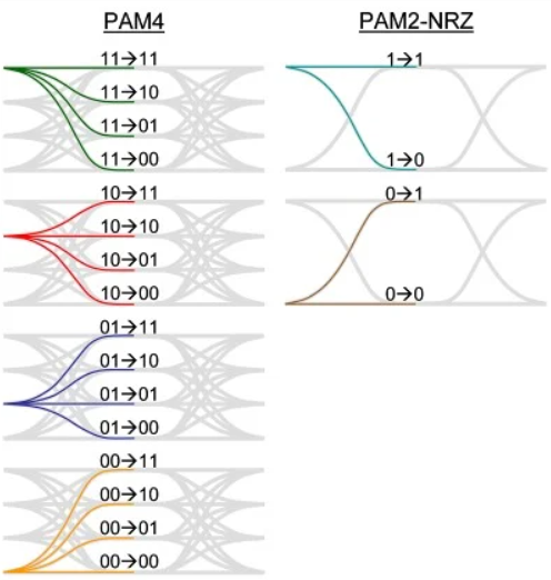
2.3 NRZ vs. PAM4: Core Differences
| Features | NRZ Technology | PAM4 Technology |
|---|---|---|
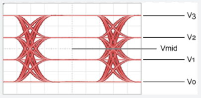
| Encoding | 2 levels (0/1), 1 bit/symbol | 4 levels (-3,-1,+1,+3), 2 bits/symbol |
| Bandwidth Efficiency | 1x (Baseline) | 2x (Double NRZ at same baud rate) |
| Voltage Swing | Full-scale (High noise margin) | 1/3 of NRZ (Denser constellation) |
| Raw BER | 1e-12 (Excellent) | 1e-4–1e-6 (Requires correction) |
| Signal Processing | Basic equalization sufficient | Needs FFE/DFE + Advanced FEC |
| Power Consumption | Lower (Simple circuitry) | Higher (DSP-intensive) |
| Cost Factor | Low (Mature technology) | Moderate (Complex components) |
| Primary Applications | 25G/50E Ethernet, PCB traces | 100G+/400G+ optics, Data center fabrics |
| Future Roadmap | Legacy maintenance | Coherent PAM4 for 1.6T+ systems |
3.Core Technologies of PAM4
3.1 High-Performance Optoelectronic Devices and Drivers
3.1.1 Optical Transmitters
-
Short-distance transmission primarily employs 20GHz-bandwidth VCSEL lasers, leveraging their narrow linewidth to minimize chromatic dispersion.
-
Medium/long-distance transmission requires external modulators to ensure linear modulation at 53.1GBaud+ baud rates, preventing bit error rate increases caused by level distortion.
3.1.2 Optical Receivers
- High-sensitivity detection and linear amplification are achieved using PIN or APD photodetectors with high responsivity for weak-signal recovery.
3.1.3 Driver Circuits
-
Analog Approach: Combines two NRZ signals to generate four-level waveforms via precision resistor networks—cost-effective but relying on precision resistor networks for linearity.
-
Digital Approach: Utilizes high-speed DACs to directly output 0/1/2/3 levels, offering superior timing accuracy for ultra-high-speed scenarios exceeding 112Gbps.
-
Both methods address impedance matching and power noise suppression, employing differential signaling to reduce crosstalk and ensure sharp, consistent level transitions.
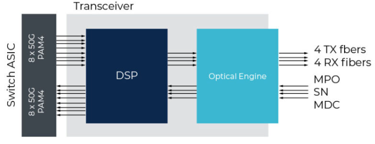
3.2 Advanced DSP Technology
3.2.1 Key DSP Functions
-
Pre-Equalization (Tx): Pre-compensates for known channel impairments.
-
Adaptive Post-Processing (Rx): Combats high-frequency attenuation, reflections, and crosstalk via ADC-digitized signal reconstruction, reopening collapsed eye diagrams.
-
Symbol Decision: Precisely decodes distorted signals into correct 4-level symbols.
3.2.2 Core Value of DSP
-
Forward Error Correction (FEC): Elevates raw BER from ~1E-4 to commercial-grade 1E-12.
-
Advanced Clock Recovery algorithms and digital Phase-locked Loop (PLL): Extracts low-jitter clocks from degraded data streams, ensuring system synchronization.
-
Power-Performance Tradeoffs: Next-gen DSP cores leverage advanced semiconductor processes to deliver trillion-operations-per-second throughput at minimal power, enabling deployable, nanosecond-latency systems.