 English
Introduction
In fiber optic communication systems, the stability and integrity of signal transmission depend directly on the quality of the fiber connection, and connector polishing is one of the core factors that determines connection performance. As 5G, high-speed data center interconnection, and other bandwidth- and distance-intensive applications continue to evolve, interference caused by optical signal reflection has become increasingly prominent. Return loss, as a key indicator of connection quality, is therefore critically important.
PC, UPC, and APC are the three mainstream fiber connector polishing types used today. Among them, APC connectors are widely used in scenarios with strict signal quality requirements because of their superior anti-reflection performance. This article takes a closer look at the technical value of fiber polishing and systematically compares the core differences among these three polishing types.
1. Technical Fundamentals of Fiber Polishing
1.1 The Core Function of Fiber Polishing
The core component of a fiber optic connector is the ceramic ferrule, and the polishing quality of its end face directly determines the contact condition when two fibers are mated. High-quality polishing minimizes surface defects, reduces or even eliminates mating gaps, and ensures that optical signals are transmitted with the lowest possible loss. By contrast, rough or non-standard polishing can lead to poor end-face contact, which not only increases insertion loss but also causes severe high-speed signal reflection. When reflected signals overlap with incident signals, they interfere with normal transmission, resulting in signal distortion, higher bit error rates, and even instability across the entire communication system.
1.2 Key Influencing Factors
The ferrule geometry is the core physical factor affecting polishing performance, mainly including parameters such as end-face radius of curvature, apex offset, and fiber height. According to international standards such as GR-326-CORE and IEC 61300-3-47, these parameters must be controlled within strict ranges to ensure connection performance. For example, UPC and PC connectors use a slightly convex spherical polish design. By precisely controlling the radius of curvature, the fiber core is positioned at the highest point of the curve to achieve tight physical contact. APC connectors, on the other hand, add an 8° angled end face on top of the spherical polish, fundamentally changing the path of reflected light.
The polishing process itself also directly determines final quality. At present, the two mainstream methods are manual polishing and automated polishing. Manual polishing is affected by limited pressure and speed control accuracy, making it difficult to ensure consistency in batch production. Automated polishing equipment, however, can precisely control process parameters and polish dozens of connectors at the same time, significantly improving polishing accuracy and consistency. It is the preferred process for high-performance applications. In addition, consumable-related factors such as polishing pad hardness and polishing slurry particle distribution also affect end-face smoothness and geometric precision.
1.3 Core Evaluation Metrics
Return loss, also known as reflection loss, is a key indicator used to measure reflected signal strength. It is defined as the ratio of reflected optical power to incident optical power and is expressed in decibels (dB). Because reflected light interferes with signal transmission, the lower the reflected signal strength, the better the connection performance.
Optical return loss (ORL) is the application-specific expression of return loss in fiber optic communications, and its value is directly affected by polishing quality. The smoother the end face and the tighter the contact, the less reflected light is generated, and the better the ORL performance. For example, a connector with ordinary flat polishing typically has an ORL of around -14 dB, while standardized PC polishing can improve it to -40 dB. UPC and APC polishing can further optimize this metric to meet the performance requirements of different applications. In systems such as WDM and PON, ORL is one of the core design indicators. If poor polishing causes ORL to fall below the required standard, the system may fail to operate properly.
2. PC vs. UPC vs. APC: Technical Comparisons
2.1 End-Face Design and Polishing Precision
The core differences among PC, UPC, and APC come from their end-face geometry design and polishing precision:
PC (Physical Contact): PC uses a micro-spherical polishing process, giving the end face a slightly convex arc shape, with the fiber core located at the highest point of the curve. The goal is to reduce the air gap during mating and achieve physical contact. PC polishing has relatively lower requirements for surface finish and was the mainstream polishing method in the early stage of fiber connector development. Today, it is mainly used in multimode fiber applications with lower performance requirements.
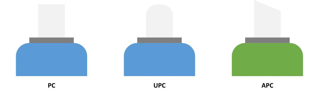
UPC (Ultra Physical Contact): UPC improves the end-face polishing process and surface finish based on PC polishing. Its end-face curvature is slightly greater than that of PC, forming a dome-shaped profile that enables tighter physical contact. UPC polishing also requires stricter control of ferrule geometry parameters, with tighter tolerances for apex offset, radius of curvature, and related metrics, effectively reducing reflected signals caused by contact gaps.
APC (Angled Physical Contact): APC uses an 8° angled polish design. While still achieving physical contact, it redirects reflected light into the fiber cladding through the angled end face, greatly suppressing reflected signals by design. APC polishing requires not only a precise angle but also a highly smooth end face, making it the most complex process among the three types.
2.2 Performance Differences
The performance differences between UPC and APC are mainly reflected in return loss and high-speed signal reflection suppression:
Return loss values: The typical return loss of a PC connector is -40 dB. UPC improves polishing precision and raises return loss performance to -55 dB or better. With its angled design, APC can achieve an industry-standard return loss of -65 dB, and some high-end products can reach even lower values. From this comparison, APC clearly has the strongest advantage in suppressing reflected signals.
High-speed signal compatibility: In 100G and higher-speed transmission scenarios, the signal wavelength becomes shorter, and the interference caused by reflected signals is amplified dramatically. UPC can meet the needs of medium- to high-speed applications, but in ultra-high-speed environments, reflected signals may still increase the bit error rate. APC, with its low-reflection characteristics, can effectively avoid reflection interference and is the preferred choice for ultra-high-speed and long-distance transmission scenarios.
Insertion loss comparison: The typical insertion loss requirement for all three polishing types is below 0.3 dB. Since UPC and PC have non-angled end faces, their contact gap is usually smaller, so insertion loss is often slightly lower than that of APC. However, in real-world applications, this difference is far less significant than the difference in return loss, so insertion loss is not the primary selection criterion in high-performance scenarios.
2.3 Visual Identification
To simplify engineering deployment and connector selection, the industry uses standardized connector colors to identify polishing types, which is why green vs. blue fiber connectors are commonly used for quick recognition. PC and UPC connectors usually have blue housings, while APC connectors typically use green housings. This marking rule applies to mainstream connector types such as SC, LC, and FC, and is the most intuitive method for quickly identifying polishing type in the field.
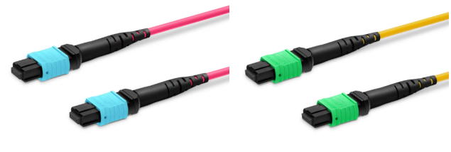
It should be noted that color coding corresponds only to polishing type and is not directly related to fiber type. For example, a blue UPC connector may be used for either single-mode fiber or multimode fiber, while a green APC connector is mainly used for single-mode fiber. In engineering practice, both fiber type and polishing type must be considered together to avoid incorrect selection.
