 English
Introduction
In modern data center architectures, the deployment model of rack-level network switches directly determines system performance, operational efficiency, and scalability. Top-of-Rack (ToR) and End-of-Row (EoR) switches are two mainstream deployment solutions. ToR switches are installed directly adjacent to server racks, minimizing the connection distance between servers and switches. In contrast, EoR switches are centrally deployed at the end of cabinet rows, achieving network aggregation through unified uplinks. This article provides an in-depth comparison of ToR and EoR switches, focusing on their core differences, performance metrics, and cabling logic.
1. Core Analysis of ToR and EoR Switch Deployment Architectures
1.1 ToR Switch Deployment Architecture
A Top-of-Rack (ToR) switch is designed with the rack as an independent network unit, where the access-layer switch is deployed at the top or end of a server rack. In this architecture, each server within the rack connects to the local ToR switch via short-distance copper or fiber cables. The ToR switch then links to the data center's aggregation or core network through uplink ports.
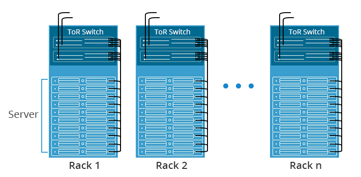
The core design principle of the ToR architecture is to minimize the link distance between servers and switches, reducing signal attenuation and transmission latency while enabling rack-level network isolation and independent management. This deployment model suits high-density server cluster scenarios, significantly improving intra-rack data exchange efficiency. Additionally, it allows for on-demand network expansion for individual racks without disrupting the overall data center network layout.
1.2 EoR Switch Deployment Architecture
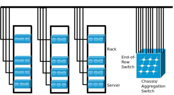
The End-of-Row (EoR) switch deployment architecture follows a centralized network access principle, where high-performance access switches are clustered at one end of a server cabinet row. In this model, all servers within the same row connect to the EoR switch via longer horizontal cabling, which then aggregates traffic through uplinks to the core network.
1.3 Core Differences Between ToR and EoR Architectures
| Comparison Dimension | ToR (Top-of-Rack) Architecture | EoR (End-of-Row) Architecture |
|---|---|---|
| Deployment Model | Distributed - Dedicated switch per rack | Centralized - Shared switch per cabinet row |
| Connection Logic | Direct server-to-switch connections (short links, low latency) | Multi-rack aggregation (longer cabling, transmission loss) |
| Management Approach | Rack-level autonomy (flexible upgrades) | Centralized control (uniform policy enforcement) |
| Scalability | Per-rack expansion capability | Row-level scaling limitations |
| Cost Structure | Higher switch count but reduced cabling costs | Lower switch count but increased cabling expenses |
| Typical Use Cases | High-performance computing, AI/ML workloads | Enterprise data centers, storage networks |
2.Key Comparisons Between ToR and EoR Deployment Architectures
2.1 Core Performance
| Comparison Dimension | ToR (Top-of-Rack) Architecture | EoR (End-of-Row) Architecture |
|---|---|---|
| Performance | • Features short direct links between servers and switches, minimizing latency and signal attenuation. • Easily matches the bandwidth demands of high-density server clusters, making it ideal for low-latency HPC applications. | • Uses a centralized aggregation model, where a single switch handles traffic from multiple racks, potentially causing bandwidth bottlenecks under high concurrency. • However, its simplified forwarding paths reduce network complexity. |
2.2 Deployment Efficiency
| Comparison Dimension | ToR (Top-of-Rack) Architecture | EoR (End-of-Row) Architecture |
|---|---|---|
| Efficiency | • Supports rack-level independence—adding a new rack only requires configuring its local ToR switch without altering the overall network topology. • Fast deployment cycles and high flexibility. | • Requires pre-planned horizontal cabling and switch configuration across an entire row, leading to higher initial setup effort. • Best suited for batch-deployment data center scenarios. |
2.3 Rack Cabling Efficiency
| Comparison Dimension | ToR (Top-of-Rack) Architecture | EoR (End-of-Row) Architecture |
|---|---|---|
| Cabling Efficiency | • Uses short intra-rack cabling (1–3m), reducing cable clutter and eliminating the need for horizontal cable trays. • Cleaner cable management with minimal interference. | • Relies on long horizontal cabling, where all server cables converge at the row's end. • Higher cable density, demanding precise tray capacity and routing planning. |
2.4 Operational Complexity
| Comparison Dimension | ToR (Top-of-Rack) Architecture | EoR (End-of-Row) Architecture |
|---|---|---|
| Operational Complexity | • Enables rack-level fault isolation—issues in one rack do not affect others, simplifying troubleshooting. | • A single switch failure can disrupt an entire row, requiring complex multi-rack cable tracing and increasing maintenance costs. |
2.5 Deployment Costs
| Comparison Dimension | ToR (Top-of-Rack) Architecture | EoR (End-of-Row) Architecture |
|---|---|---|
| Deployment Costs | • Higher switch procurement costs (one per rack) but saves on cabling and tray expenses due to short links. | • Lower switch costs (fewer devices) but higher cabling/tray investments for long horizontal runs. |
2.6 Scalability Adaptability
| Comparison Dimension | ToR (Top-of-Rack) Architecture | EoR (End-of-Row) Architecture |
|---|---|---|
| Scalability & Adaptability | • Highly flexible expansion—adding servers/racks only requires upgrading the local ToR switch, without impacting other racks. • Ideal for fast-evolving business needs. | • Limited by the central switch's port density—scaling up often requires replacing the entire EoR switch, leading to longer lead times and cost volatility. |
3. Switch Selection in Data Center Scenarios
3.1 Deployment Strategies for Different Business Scenarios
The selection between ToR (Top-of-Rack) and EoR (End-of-Row) architectures is primarily driven by specific workload requirements.
For low-latency demanding scenarios such as High-Performance Computing (HPC) and AI training clusters, the ToR architecture is the clear choice here due to its ultra-low latency characteristics. The direct server-to-switch connections minimize signal propagation delays, which is critical for tightly-coupled parallel computations. The rack-level isolation also allows for independent scaling of compute resources without disrupting the entire cluster.
For enterprise-level integrated data centers, the EoR's centralized management model proves more effective for conventional business applications. The reduced number of access switches simplifies network operations while maintaining sufficient performance for most enterprise workloads. The standardized cabling approach also facilitates easier maintenance in environments where IT staff may have limited networking expertise.
For Edge Computing Deployments, the compact nature of ToR makes it ideal for space-constrained edge locations. Each rack operates as a self-contained unit, reducing dependencies on centralized network resources that may be unavailable in remote deployments.
3.2 Comparison of ToR and EoR Switch Deployment Scenarios
The core suitability of ToR architecture lies in high-density, highly dynamic data center environments, such as compute node zones in hyperscale cloud data centers or high-frequency trading rooms in the financial sector. These scenarios are sensitive to network latency and require frequent rack-level server expansion or reduction. ToR's independent management capability mitigates impact on the overall network.
The EoR architecture is better suited for medium-sized data centers with organized server layouts and stable business requirements, such as non-core service rooms in government agencies or universities. These scenarios prioritize equipment cost control and operational efficiency. EoR's centralized deployment reduces the number of access layer switches, lowering equipment procurement costs and minimizing space requirements in the equipment room. Furthermore, for scenarios prioritizing network architecture flattening and facilitating global traffic monitoring, EoR's aggregated link design offers distinct advantages.
