 English
With the rapid development of Artificial Intelligence (AI) technology, AI data training and applications often involve massive data transmission and real-time interaction, leading to an explosive growth in demand for computing power and network capacity. Optical modules, as the "couriers" that transmit data between devices in the network, bear the heavy responsibility of sending and receiving massive data for the "computing power highway," making their importance increasingly prominent. This article will systematically introduce the definition, composition, rate evolution, form factors, transmission modes, wavelength, optical power, interface types, and the latest technological trends of optical modules.
What is an Optical Module
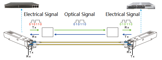
An optical module is a device that converts electrical signals into optical signals and vice versa. Its main function is to convert an electrical signal into an optical signal at the transmitting end, transmit it through an optical fiber, and then convert the optical signal back into an electrical signal at the receiving end. Through optical modules, seamless connection and collaboration between various types of equipment can be achieved. For example, network routers, switches, servers, and storage devices all rely on optical modules for interconnection. Optical modules are widely used and are core components in building computing power infrastructure.
Composition of an Optical Module
An optical module typically consists of an optical transmitter assembly, an optical receiver assembly, a high-speed DSP chip (applicable to 100G/200G/400G/800G PAM4) , an optical interface, a base, a circuit board, and electrical interface gold fingers.
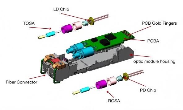
Figure 2: Composition of an Optical Module
| Component | Function |
|---|---|
| Optical Interface | Connection port for the optical fiber, used for transmitting and receiving optical signals. |
| Optical Transmitter Assembly | Contains the laser chip, used for processing electrical signals and driving the laser to modulate and output optical signals according to the electrical signal. |
| Optical Receiver Assembly | Contains the photodetector chip, which converts the received optical signal into an electrical signal through the photodetector chip. |
| Electrical Interface Gold Fingers | Composed of multiple golden conductive contacts, achieving two main functions. |
| Circuit Board | Serves as the carrier for various components and chips of the optical module to interconnect and work collaboratively. |
Modern high-speed modules (400G/800G/1.6T) widely adopt COB (Chip on Board) packaging technology to improve integration, heat dissipation, and optoelectronic performance.
Data Rate of Optical Modules
The interface rate of an optical module refers to the number of bits transmitted per second, with units including Mbps, Gbps, and Tbps.
Currently, the main transmission rates for optical modules include: 1Gbps, 10Gbps, 25Gbps, 40Gbps, 100Gbps, 200Gbps, 400Gbps, 800Gbps, and 1.6Tbps. With the expansion of AI cluster scale, 800G and 1.6T optical modules are becoming the mainstream for the new generation of computing power networks.
Form Factor of Optical Modules
Form factor can be simply understood as the appearance and interface form of the optical module. The standards are determined by standardization organizations, ensuring that optical modules produced by different manufacturers are compatible and interoperable. The most frequently used standardization organizations in the optical module industry are IEEE (Institute of Electrical and Electronics Engineers) and MSA (Multi-Source Agreement). MSA is essentially a multi-vendor specification that complements the IEEE standards.
The common optical module form factors currently specified by standardization organizations include:
- GBIC → SFP → SFP+ → SFP28(1G/10G/25G)
- QSFP+、QSFP28、QSFP56(40G/100G/200G)
- CFP/CFP2/CFP4/CFP8(Traditional 100G/200G/400G)
- QSFP-DD(400G/800G)
- OSFP(400G/800G/1.6T)
SFP (Small Form-Factor Pluggable): SFP optical modules can be understood as an upgraded version of GBIC modules (the first packaging standard defined by MSA). SFP modules support hot-pluggable, and their volume is reduced by half compared to GBIC modules. SFP modules support Gigabit and Fast Ethernet rates.
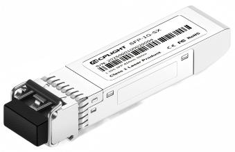
Figure 3: AICPLIGHT 1000BASE-SX SFP Optical Transceiver Module (P/N: SFP-1G-SX)
SFP+ (Small Form-factor Pluggable Plus): SFP+ and SFP modules have the same physical dimensions. The difference is that SFP+ modules have lower power consumption and higher rates, supporting 10 Gigabit Ethernet (10Gbps).
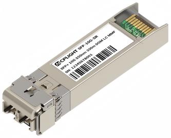
Figure 4: AICPLIGHT 10GBASE-SR SFP+ Optical Transceiver Module (P/N: SFP-10G-SR)
SFP28 (Small Form-factor Pluggable 28): SFP28 is an upgraded version of SFP+ with the same physical dimensions. SFP28 modules support a single channel rate of 25Gbps.
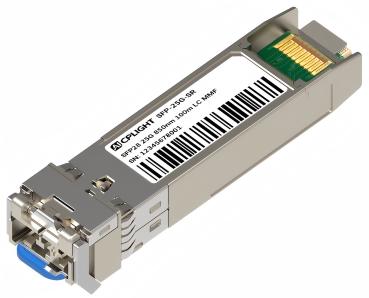
Figure 5: AICPLIGHT 25GBASE-SR SFP28 Optical Transceiver Module (P/N: SFP-25G-SR)
QSFP+ (Quad Small Form-factor Pluggable Plus): QSFP+ modules support 4-channel transmission simultaneously. The single-channel rate can support 10Gbps, achieving a total rate of 40Gbps through 4-channel transmission.
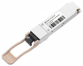
Figure 6: AICPLIGHT 40GBASE-SR4 QSFP+ Optical Transceiver Module (P/N: QSFP-40G-SR4)
QSFP28 (Quad Small Form-factor Pluggable 28): QSFP28 modules support 4-channel transmission simultaneously. The single-channel rate can support 25Gbps, achieving a rate exceeding 100Gbps through 4-channel transmission. QSFP28 has the same physical dimensions as QSFP+, but different rates.
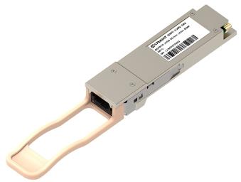
Figure 7: AICPLIGHT 100GBASE-SR4 QSFP28 Optical Transceiver Module (P/N: QSFP-100G-SR4)
QSFP56 (Quad Small Form-factor Pluggable 56): QSFP56 modules also support 4-channel parallel transmission. The single-channel rate is upgraded to 50Gbps (using PAM4 modulation technology), achieving a total rate of 200Gbps through 4-channel collaborative transmission. It is a core optical module type for mid-to-high-speed network scenarios. QSFP56 maintains the same physical dimensions and interface as QSFP28 and QSFP+, ensuring compatibility with existing QSFP-series encapsulated equipment ports.
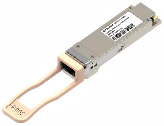
Figure 8: AICPLIGHT 200GBASE-SR4 QSFP56 Optical Transceiver Module (P/N: Q56-200G-SR4)
CFP/CFP2/CFP4/CFP8 (C Form-factor Pluggable): CFP modules have a transmission rate range of 100Gbps to 400Gbps. CFP was designed based on SFP but has a larger physical size than SFP. CFP / CFP2 / CFP4 were initially used for 40G/100G and later also supported higher channel rates:
- CFP supports a single-channel rate of 10Gbps, achieving 40Gbps and 100Gbps through 4×10Gbps and 10×10Gbps.
- CFP2 is half the size of CFP, achieving 100Gbps and 200Gbps through 4×25Gbps and 8×25Gbps.
- CFP4 is a quarter of the size of CFP, achieving 100Gbps and 200Gbps through 4×25Gbps and 8×25Gbps.
- CFP8 is a package type designed for 400G, achieving 400Gbps through 16×25Gbps and 8×50Gbps.
QSFP-DD (Quad Small Form-factor Pluggable-Double Density): QSFP-DD packaging is compatible with QSFP+/QSFP28 and other QSFP packages. It doubles the QSFP's 4 channels by adding a second row of contacts, supporting 8 channels simultaneously. The single-channel rate can reach 50Gbps or 100Gbps, thus QSFP-DD modules can support 400Gbps or 800Gbps rates.
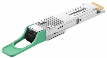
Figure 9: AICPLIGHT 400GBASE-FR4 QSFP-DD Optical Transceiver Module (P/N: QDD-400G-FR4)
OSFP (Octal Small Form-factor Pluggable): OSFP modules have 8 high-speed electrical channels. Through single-channel rate configurations of 25Gbps/50Gbps/100Gbps/200Gbps, it can achieve total bandwidths of 200Gbps, 400Gbps, 800Gbps, and 1.6Tbps.
As the performance and transmission bandwidth of optical modules continuously increase, the packaging methods of optical modules are also evolving in the direction of higher transmission rates, smaller size, lower power consumption, and higher density.
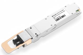
Figure 10: AICPLIGHT 800GBASE 2xSR4 OSFP Optical Transceiver Module (P/N: OSFP-800G-2xSR4)
Transmission Distance of Optical Modules
The transmission distance of an optical module is divided into short-haul, medium-haul, and long-haul. Generally, 2 km and below are considered short-haul, 2 km to 30 km are medium-haul, and 30 km and above are long-haul (the specific distance is subject to the transmission distance marked on the optical module model). The actual distance that an optical module can transmit is limited primarily by loss and dispersion as the optical signal travels through the fiber.
Loss: Refers to the phenomenon where the intensity of the optical signal gradually weakens during transmission in the optical fiber medium. It is expressed in dB/km. The loss of optical signals mainly comes from absorption loss of the fiber material, scattering loss, bending loss, and connector/splice loss. Generally, single-mode fiber has less loss compared to multimode fiber.
Dispersion: Refers to the phenomenon where light signals of different frequencies or different modes travel at different speeds in the optical fiber, causing the optical pulse to broaden, which leads to signal distortion. It is expressed in ps/(nm·km). Dispersion can cause adjacent pulses to overlap, increasing the bit error rate and limiting the maximum transmission rate and unrepeated transmission distance of the optical fiber.
Transmission Mode of Optical Modules
Based on the transmission mode of optical signals in the fiber, optical fibers can be divided into single-mode fiber (SMF) and multimode fiber (MMF). To accommodate different types of fibers, optical modules are also divided into single-mode optical modules and multimode optical modules.
Single-Mode Optical Module: Used with single-mode fiber. Single-mode fiber has a thinner core, transmits signals using a single mode of light, has less dispersion during transmission, and a large transmission capacity, typically used for long-distance transmission.
Multimode Optical Module: Used with multimode fiber. Multimode fiber has a thicker core, transmits signals using multiple different modes of light, has greater dispersion during transmission, and its transmission performance is worse than single-mode fiber, but the cost is low, making it suitable for smaller capacity, short-distance transmission.
Center Wavelength of Optical Modules
The center wavelength refers to the optical band used for optical signal transmission, measured in nm (nanometers). The longer the center wavelength, the smaller the loss of the optical signal in the fiber, and the longer the transmission distance.
The three main center wavelengths commonly used by optical modules are: 850nm band, 1310nm band, and 1550nm band.
| Wavelength Band | Application Scenario |
|---|---|
| 850 nm | Mainly used for multimode modules, low cost but short transmission distance. Usually within a few hundred meters, such as for local area network connections. |
| 1310 nm | Suitable for single-mode modules, suitable for medium-to-long distance transmission. Generally for transmission distances within 40 km, such as connections within a metropolitan area network. |
| 1550 nm | Suitable for single-mode modules, suitable for long-distance transmission over 40 km. Can achieve unrepeated transmission up to 120 km. |
In addition to the above three bands, there are CWDM and DWDM bands used for wavelength division multiplexing (WDM) systems.
| Wavelength Name | Wavelength Range | Application Scenario |
|---|---|---|
| CWDM (Coarse Wavelength Division Multiplexing) | Wavelength range from 1270nm to 1610nm, with a channel spacing of 20nm. | Used for coarse wavelength division multiplexing systems, suitable for medium-to-short distance transmission. |
| DWDM (Dense Wavelength Division Multiplexing) | C-band (Conventional band), 1530nm to 1565nm; L-band (Long wavelength band), 1565nm to 1625nm. | Dense wavelength division multiplexing has a smaller channel spacing, usually 0.8 nm, used for long-distance and large-capacity transmission. |
Both CWDM and DWDM modules are referred to as "color light" optical modules on devices. These modules transmit data using light of different colors (i.e., different wavelengths), where each color represents an independent data channel, thereby enabling the transmission of multiple wavelength signals over a single optical fiber. This technology significantly increases the transmission capacity and efficiency of the fiber.
In contrast, the 850nm, 1310nm, and 1550nm bands are also known as "grey light" or "black and white light" due to their relatively single center wavelength. Unlike color light modules, grey light modules do not use complex wavelength division multiplexing technology but focus on providing stable and reliable single-wavelength transmission. This characteristic makes them more suitable for short-distance, low-cost network connections, such as in IP network scenarios.
Optical Power of Optical Modules
Optical module power is one of the core parameters for measuring the performance of an optical module. It includes metrics such as transmit optical power, receive optical power, overload optical power, and receiver sensitivity. These directly affect the stability and transmission quality of the optical communication system.
- Transmit Optical Power: Refers to the intensity of light emitted by the light source at the sending end of the optical module, measured in dBm. The transmit optical power needs to remain stable to ensure signal transmission quality.
- Receive Optical Power: Represents the average optical power range that the receiving end can recognize. Its lower limit is the maximum receiver sensitivity, and its upper limit is the overload optical power, measured in dBm.
- Overload Optical Power: Also known as saturation optical power, it refers to the maximum input optical power that the receiving end of the optical module can withstand, measured in dBm. When the received optical power is greater than the overload optical power, it can cause bit errors or even damage to the equipment.
- Receiver Sensitivity: Refers to the minimum receivable optical power of the optical module under the condition of satisfying a certain bit error rate, measured in dBm.
Interface Types of Optical Modules
This refers to the physical connector type when the optical module interfaces with the optical fiber. Common connector types include SC, LC, and MPO.
SC (Square Connector): A standard square optical fiber connector with good stability and durability. SC interfaces were originally designed for user-end equipment in access networks but are now also widely used in various network environments.
LC (Little Connector): A small-form-factor optical fiber connector. LC interfaces have a small size and high precision. LC interfaces can be used for single-mode or multimode fiber and are widely applied in high-density cabling environments such as data centers and telecommunication networks.
MPO (Multi-fiber Push On): A multi-fiber connector that can simultaneously connect multiple optical fibers. MPO interfaces are typically used for parallel data transmission in high-density cabling environments, such as server interconnections within data centers or high-speed links between switches.
Naming of Optical Modules
Different manufacturers have their own rules for naming optical modules. Organizations like IEEE and MSA also provide specifications and standards for optical module naming. Taking 100G optical modules as an example, the naming convention defined by IEEE 802.3 is shown in the figure below:
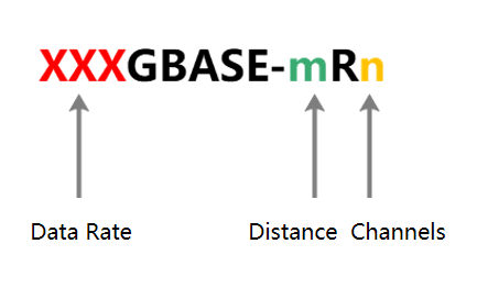
Figure 11: Optical Module Naming Standard
The values for each parameter in the 100G optical module naming are shown in the table below:
| Code | Meaning | Description |
|---|---|---|
| XXX | Rate | For example, 100 represents a rate of 100G. |
| mR | Transmission Distance | Uses a 2-letter code to indicate the transmission distance. • SR indicates short-reach, with a transmission distance from tens to hundreds of meters, typically 100m. • DR is a non-IEEE standard, indicating a transmission distance of 500m. • FR is a non-IEEE standard, indicating a transmission distance of 2km. • LR indicates long-reach, with a transmission distance of 10km. • ER indicates extended-reach, with a transmission distance of 40km. • ZR is a non-IEEE standard, indicating a transmission distance of 80km. |
| n | Number of Channels | A number, for example, 4, 8, 10. • 4 indicates the module supports 4 channels. • 8 indicates the module supports 8 channels. • 10 indicates the module supports 10 channels. |
For example, a 100G optical module named 100GBASE-LR4 means the optical module has a rate of 100 Gbps, supports a transmission distance of 10 km, and supports 4 channels.
In actual use, some manufacturers' optical module names also include the packaging type, such as QSFP-100G-SR4. QSFP indicates the packaging type is QSFP28, 100G indicates the optical module's interface rate, SR4 indicates the transmission distance is 100m and supports 4 channels.
In summary, the naming of optical modules varies among manufacturers, but the naming rules usually contain information such as packaging type, transmission rate, fiber type, transmission distance, and operating wavelength.
New Technologies in Optical Modules
The core of optical module manufacturing lies in packaging technology. Currently, COB (Chip on Board) is the mainstream packaging solution for high-speed optical modules. COB significantly enhances integration by directly mounting bare chips (optical and electrical chips) onto the PCB substrate and using wire bonding for electrical connections. It also boasts advantages such as small size, good heat dissipation, and low cost, making it widely used in 400G and 800G high-speed modules.
To meet the network demand for higher bandwidth and lower power consumption, optical module technology is continuously evolving along a clear path. The main directions include the following three key technologies:
| Name | Principle Introduction | Advantages and Applications |
|---|---|---|
| LPO (Linear-drive Pluggable Optics) | LPO removes the DSP chip within the module and shifts some signal processing tasks to the switch chip, using linear drive technology to directly control the laser, simplifying the module structure. | LPO technology can reduce power consumption by over 50%, and latency is lower. LPO is a short-term optimization solution, suitable for short-distance data center connection scenarios (such as within a rack), but requires high channel quality. |
| Silicon Photonics | Based on mature CMOS process technology, integrating photonic components (such as modulators, detectors, and WDM devices) on a silicon substrate, using optical signals to replace traditional copper wire transmission of data. | This technology combines the low power consumption characteristics of photonics with the low-cost advantages of the silicon-based process, aiming to achieve optoelectronic integration and fabricate optical circuits like integrated circuits. |
| CPO (Co-Packaged Optics) | Co-packaging the switch chip (ASIC) and the optical engine (Silicon Photonics chip) on the same baseboard, greatly shortening the electrical signal transmission path. | CPO is the best comprehensive packaging solution for realizing high integration, low power consumption, low cost, and high-speed modules in the future. It is currently in the early stages of industrialization and is expected to become the mainstream in the 3.2T/6.4T capacity era. |
Conclusion
Currently, with the acceleration of computing infrastructure construction driven by AI, the demand for high-speed optical modules used for data center optical interconnection is growing significantly. 400G optical modules are widely used, 800G optical modules have been commercialized on a large scale, and 1.6T optical modules have entered the mass production stage.
In the future, driven by AI and computing power networks, optical modules will inevitably accelerate their development towards higher speed, lower power consumption, smaller size, and more intelligent integration. CPO and Silicon Photonics technology are likely to become the core engines for the future development of optical modules.
