As AI training, large-scale inference, and high-performance computing continue to scale, modern data centers increasingly adopt 400G spine links combined with 200G server access. In multimode environments, passive MPO fan-out (Y-cable) architectures are widely used to optimize bandwidth utilization and deployment cost.
However, many operators encounter a puzzling issue:
all components appear compatible, yet the optical link never comes up.
In most cases, link failures are not caused by faulty hardware or vendor incompatibility, but by lane-level architectural mismatches that aggregate bandwidth figures fail to reveal. This article analyzes a real-world deployment failure, explains the fundamental compatibility rules of optical modules, and outlines proven optimization paths for reliable 400G-to-200G multimode connectivity.
Typical 400G-to-200G Multimode Deployment Architecture
A common AI data center access design includes:
-
Spine / leaf uplinks: 400Gbps
-
Leaf switch ports: 400G QSFP112
-
Server NICs (e.g., NVIDIA CX7): 2 × 200G QSFP56
-
Interconnection method: Passive multimode MPO fan-out (Y-cable)
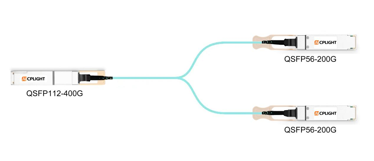
Figure 1: Typical 400G-to-200G Multimode Fan-Out Architecture (A typical AI data center access architecture where a 400G leaf switch port connects to dual 200G server NIC ports using a passive multimode MPO fan-out Y-cable.)
From an aggregate bandwidth perspective, this architecture appears perfectly balanced. Problems arise when optical modules are selected without examining lane-level compatibility.
A Common but Critical Misconfiguration
In many multimode deployments, the following optical module pairing is selected:
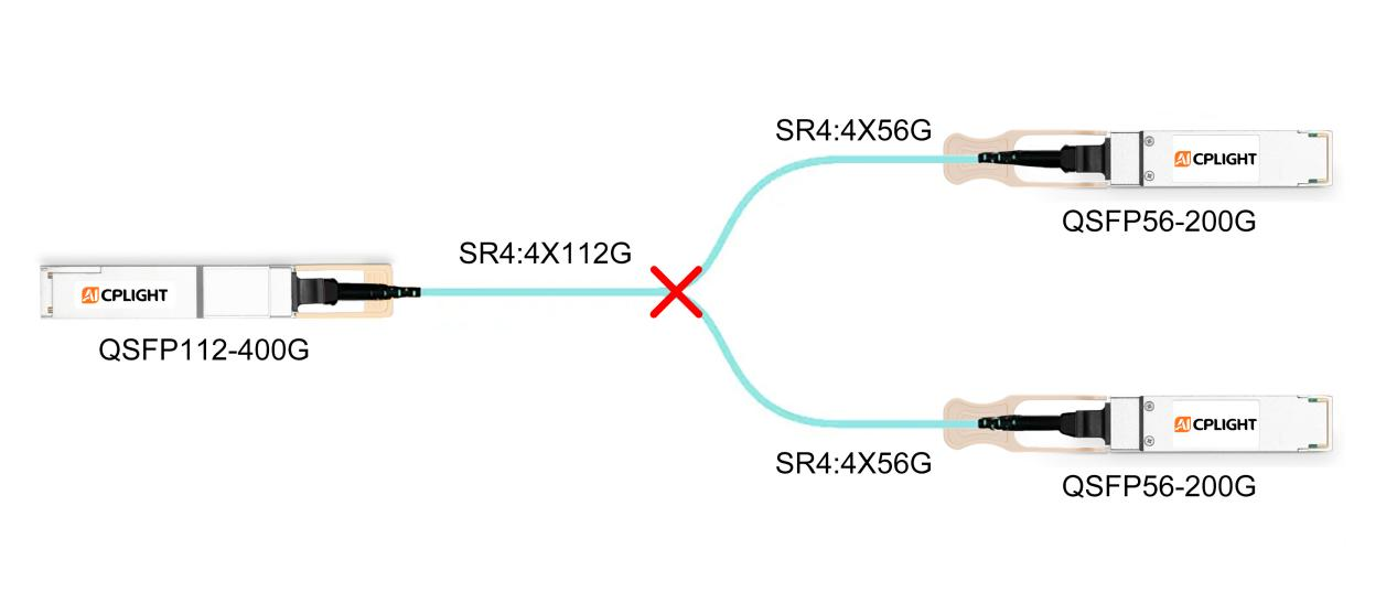
Even though the aggregate bandwidth appears to match (400G → 2 × 200G), the link often fails to reach an operational (UP) state. The failure is deterministic and rooted in the link architecture, rather than being random or vendor-related.
Figure 2: Common Misconfiguration - 400G SR4 to 2 × 200G SR4 (A mismatched multimode optical design using a 400G QSFP112 SR4 module on the switch side and two 200G QSFP56 SR4 modules on the server side, resulting in lane-level incompatibility.)
Real-World Deployment Case: When Everything Looks Right—but the Link Stays Down
During the rollout of an AI training cluster, a customer deployed 400G leaf switches connected to dual-port 200G server NICs using passive multimode fan-out cables.
All optical modules passed individual diagnostics, firmware versions were aligned, and cabling quality was verified. Despite this, the link never came up.
A lane-level analysis revealed the root cause:
No passive fan-out cable can convert optical lane speeds or reconcile incompatible fiber structures. As a result, the failure occurred at the physical layer—even though every component functioned correctly on its own.
This case highlights a critical misconception in mixed-rate designs: matching aggregate bandwidth does not guarantee optical compatibility.
Core Principles of Optical Module Compatibility
An optical module bridges electrical signals on the host side and optical signals on the fiber side. For a link to function correctly, three conditions must be satisfied simultaneously:
1.Electrical (SerDes) lane rates must be compatible
If lane rates differ, a dedicated lane-rate adaptation architecture (such as an internal Gearbox) is required.
2.Optical lane speed and lane count must match
Each optical lane must operate at the same data rate and structure on both ends of the link.
3.Fiber topology must be aligned
The number of transmit and receive fibers must match end-to-end. Passive fan-out cables cannot resolve structural mismatches.
If any one of these conditions is violated, the link will fail regardless of vendor, firmware, or configuration.
Why the Link Fails: Lane-Level Root Cause Analysis
Optical Lane Speed Mismatch
A 56G receiver cannot interpret a 112G PAM4 signal. Optical lane rates are fixed and non-negotiable.
Fiber Resource Mismatch
A passive multimode Y-cable cannot remap or multiply fiber resources to resolve this mismatch.
| Module Type |
Electrical SerDes |
Optical Lanes |
Per-Lane Speed |
Total Fibers |
Fan-out Compatibility |
| 400G QSFP112 SR4 |
4 × 112G |
4 |
112G PAM4 |
8 (4 Tx + 4 Rx) |
Not compatible with 56G SR4 |
| 200G QSFP56 SR4 |
4 × 56G |
4 |
56G PAM4 |
8 (4 Tx + 4 Rx) |
Requires 16 fibers for 2 ports |
| 400G QSFP-DD SR8 |
8 × 56G |
8 |
56G PAM4 |
16 (8 Tx + 8 Rx) |
Native fan-out to 2 × 200G |
| 200G QSFP56 SR2 |
4 × 56G |
2 |
100G PAM4 |
4 (2 Tx + 2 Rx) |
Requires internal lane remapping |
| 200G QSFP112 SR2 |
2 × 112G |
2 |
112G PAM4 |
4 (2 Tx + 2 Rx) |
112G end-to-end |
Key takeaway:
Passive fan-out works only when optical lane rate, lane count, and fiber structure are aligned.
Practical Optimization Options
Option 1: Standardize on a 56G SerDes Ecosystem
-
Replace QSFP112 switch ports with QSFP-DD
-
Use 400G QSFP-DD SR8 on switches
-
Keep 200G QSFP56 SR4 on servers
Best for: New builds prioritizing cost efficiency and ecosystem maturity.
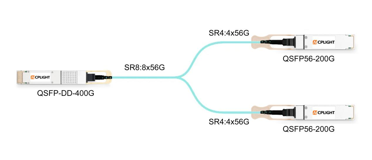
Figure 3: 56G SerDes-Based Fan-Out with 400G SR8 (A 56G SerDes-aligned fan-out solution using a 400G QSFP-DD SR8 module to natively support breakout to two 200G QSFP56 SR4 server links.)
Option 2: Introduce Lane-Rate Adaptation on the Server Side
Trade-off: Minimal architectural change, but higher module cost and power consumption.
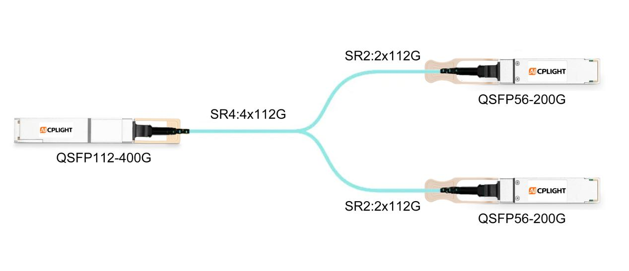
Figure 4: Lane-Rate Adaptation Using 200G SR2 Modules (A mixed-rate optical architecture where a 400G QSFP112 SR4 switch port connects to a 200G QSFP56 SR2 server module through internal lane-rate adaptation.)
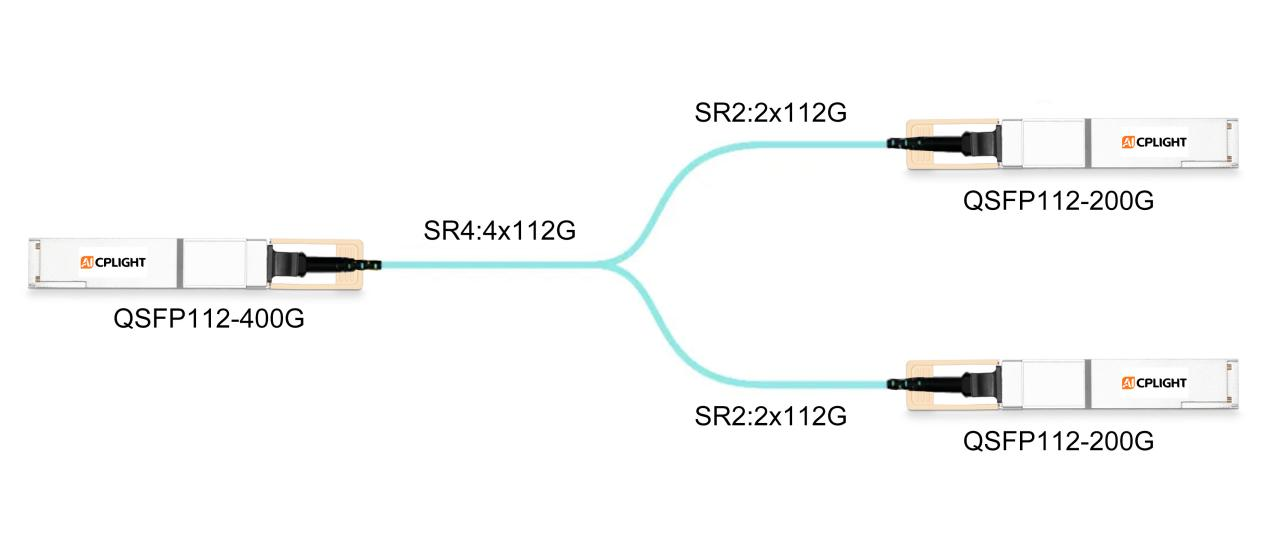
Option 3: Move to 112G SerDes End-to-End
Best for: Performance-driven environments focused on power efficiency and long-term scalability.
Figure 5: End-to-End 112G SerDes Architecture (An end-to-end 112G SerDes design using 400G QSFP112 SR4 and 200G QSFP112 SR2 modules, ensuring full lane-rate and fiber alignment.)
Conclusion
In high-speed AI data center networks, optical module selection cannot be based on aggregate bandwidth alone. Electrical SerDes rates, optical lane structures, and fiber topology must be aligned across the entire link.
By validating lane-level compatibility during the design phase, operators can avoid late-stage deployment failures, reduce rework costs, and build scalable, future-ready network infrastructures.
AICPLIGHT Technical Perspective
From AICPLIGHT's field experience supporting large-scale AI and HPC data center deployments, most optical link failures are not caused by defective hardware, but by architecture-level mismatches introduced during the design stage.
As networks transition from 56G to 112G SerDes technologies, mixed-rate environments will remain common. This makes lane-level compatibility analysis—rather than headline bandwidth—the most critical factor in optical module selection, especially in multimode fan-out scenarios.
AICPLIGHT recommends validating SerDes rate alignment, optical lane structure, and fiber topology as a unified system before deployment.
 English