 English
In the context of explosive data center bandwidth demand growth, the 400G optical transceiver has become the core support for high-density interconnects. In multimode scenarios, 400G SR4 and 400G SR8 are the two main solutions. Although both are short-reach multimode optical transceivers, they have fundamental differences in channel architecture, interface design, compatibility, and deployment cost.
400G SR4 vs. 400G SR8: Channel Architecture
The core difference between 400G SR4 and 400G SR8 stems from "how the 400G bandwidth is split". This design directly impacts their hardware adaptation and deployment flexibility.
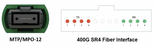
400G SR4: 4-Channel Parallel Transmission
The 400G SR4 optical transceiver adopts a 4×100Gbps PAM4 channel architecture. It transmits data through 4 pairs of optical channels in parallel, with each pair carrying a 100Gbps rate (based on PAM4 modulation technology, the single-channel symbol rate reaches 50 Gbaud). The optical interface uses an MPO-12 connector, utilizing only 8 optical fibers (4 transmit and 4 receive), with the remaining fibers reserved for redundancy. It complies with the IEEE 802.3bs standard.
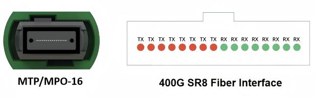
400G SR8: 8-Channel Parallel Transmission
The 400G SR8 optical transceiver adopts an 8×50Gbps PAM4 channel architecture, splitting the 400G bandwidth into 8 parallel 50Gbps channels. The single-channel symbol rate is 25 Gbaud. The optical interface uses an MPO-16 connector, requiring 16 optical fibers (8 transmit and 8 receive). 400G SR8 is an earlier 400G multimode implementation scheme that adheres to the IEEE 802.3cd standard.
400G SR4 vs. 400G SR8: Key Parameter Comparison
| Parameter | 400G SR4 | 400G SR8 |
|---|---|---|
| Channel Architecture | 4×100G PAM4 | 8×50G PAM4 |
| Single-Channel Symbol Rate | 50 Gbaud | 25 Gbaud |
| Optical Fiber Interface | MPO-12 (8 cores working, 4 cores redundant) | MPO-16 (using 16 cores) |
| Typical Power Consumption | 9–11W | 7–9W |
| Breakout Capability | Supports 4×100G / 2×200G | Pure 400G direct connection, but theoretically supports 8×50G (physically feasible, but depends on switch vendor implementation) |
| Stability | High | Higher (due to lower symbol rate) |
400G SR4 vs. 400G SR8: Scenario Adaptation
The core advantage of 400G SR4 is compatibility and splitting capability, making it particularly suitable for the following scenarios:
Existing Infrastructure Upgrade: If the data center has deployed a large number of 100G SR4 (MPO-12 interface) or 200G SR2 optical transceivers, 400G SR4 can directly reuse existing MPO-12 fiber links. This allows for a smooth upgrade from 100G/200G to 400G without replacing the fiber cabling, significantly reducing renovation costs.
Multi-Rate Mixed Deployment: 400G SR4 supports the "Breakout" splitting function. A single 400G SR4 fiber can connect 4×100G devices or 2×200G devices simultaneously. This is suitable for scenarios requiring multi-rate interconnection, such as server clusters and spine-leaf switches, improving port utilization.
Medium-to-High Density Deployment: The MPO-12 interface has higher fiber resource utilization (8 cores carry 400G). In environments with moderate cabinet port density and limited fiber resources, 400G SR4 can reduce fiber cabling complexity and lower long-term maintenance costs.
The core competitiveness of 400G SR8 is low power consumption and mature stability, making it more suitable for the following scenarios:
Pure 400G High-Speed Direct Connection: In scenarios such as direct connection between nodes in AI training clusters or supercomputing centers, 400G SR8's 25 Gbaud low symbol rate design offers stronger signal stability and a lower bit error rate. The typical power consumption of 400G SR8 is 1-2W lower than 400G SR4, making it suitable for large-scale deployment to reduce energy consumption.
High-Density, Low-Power Consumption Requirements: Under QSFP-DD or OSFP packaging, 400G SR8's low power consumption feature reduces equipment heat dissipation pressure. This is especially suitable for liquid-cooled data centers and high-density cabinet deployments, as it can increase the number of modules per cabinet and optimize space utilization.
New Data Center Pure 400G Networks: When there are no existing fiber link constraints, 400G SR8's mature technology (standardized earlier) can lower procurement costs. Furthermore, the 25 Gbaud single-channel technology has a lower barrier, and its product stability has been validated by the market over a long period, resulting in lower operation and maintenance risks.
Summary of Selection Recommendations:
| Requirement Direction | Recommended Solution | Reason |
|---|---|---|
| Pure 400G Direct Connection, Highest Stability | 400G SR8 | More channels, lower symbol rate, lower power consumption |
| Multi-Rate Mixed (100G/200G/400G) | 400G SR4 | Flexible splitting, suitable for existing architecture |
| Limited Fiber Resources | 400G SR4 | Only 8 cores are needed for transmission |
| New AI Clusters, Large-Scale HPC | 400G SR8 | Low energy consumption, mature stability |
| Need to balance future evolution capability | 400G SR4 | Higher flexibility for Breakout and network architecture |
AICPLIGHT 400G SR4/SR8 Optical Transceivers
AICPLIGHT offers a comprehensive line of 400G multimode optical transceiver products, designed to meet high-speed interconnection needs in data centers, High-Performance Computing (HPC), and AI clusters. Our 400G transceiver series covers mainstream Ethernet optical transceivers and InfiniBand optical transceivers, supporting various packaging and technical standards to ensure excellent performance and flexible deployment capabilities:
Ethernet Optical Transceivers
| Model | Description |
|---|---|
| QDD-400G-SR4 | 400GBASE-SR4 QSFP-DD PAM4 850nm 100m DOM MPO-12/APC MMF Ethernet Optical Transceiver Module |
| OSFP-400G-SR4 | 400GBASE-SR4 OSFP Flat Top PAM4 850nm 100m DOM MTP/MPO-12/APC MMF Ethernet Optical Transceiver Module |
| Q112-400G-SR4 | 400GBASE-SR4 QSFP112 PAM4 850nm 50m DOM MPO-12/APC MMF Ethernet Optical Transceiver Module |
| QDD-400G-SR8 | 400GBASE-SR8 QSFP-DD PAM4 850nm 100m DOM MPO-16/APC MMF Ethernet Optical Transceiver Module |
InfiniBand Optical Transceivers
| Model | Description |
|---|---|
| OSFP-400G-SR4 | 400GBASE-SR4 OSFP Flat Top PAM4 850nm 50m DOM MPO-12/APC MMF InfiniBand NDR Optical Transceiver Module |
| Q112-400G-SR4 | 400GBASE-SR4 QSFP112 PAM4 850nm 50m DOM MPO-12/APC MMF InfiniBand NDR Optical Transceiver Module |
Conclusion
The choice between 400G SR4 and 400G SR8 is not about "superiority versus inferiority" but "scenario versus scenario". If your core needs are compatibility with existing infrastructure and flexible splitting (100G/200G), 400G SR4 is the more cost-effective choice. If you prioritize low power consumption and stability for pure 400G direct connections, 400G SR8 is the superior option. As the price of 400G multimode optical transceivers continues to drop, the best data center interconnection solution can only be chosen by considering your cabling environment, speed requirements, and long-term planning.
